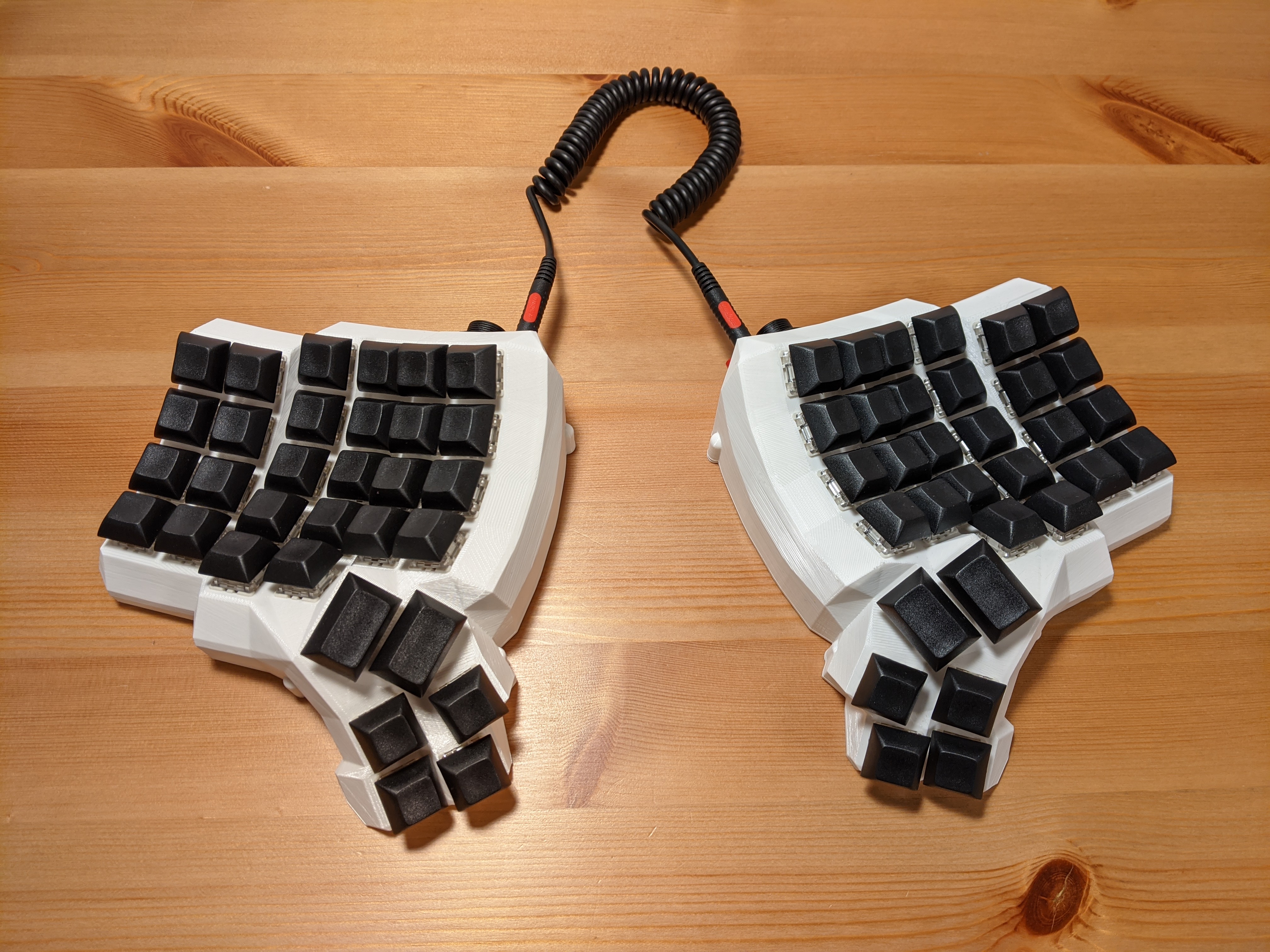
I made an ergonomic split keyboard using the Dactyl Manuform design, specifically the 5x6 version. I'm going to describe the process in the hope that it will be useful to someone considering making one. Here's what the final product looks like:
The Dactyl Manuform, made by Tom Short, is a modification of the original Dactyl keyboard design by Matthew Adereth. Matthew has given an entertaining talk on his design process. It won't really help with building the keyboard, but it has some nice bits on keyboard history in general.
The keyboard is controlled by an Arduino Pro Micro (one in each half) which is running the QMK firmware. This firmware is used by many keyboards, both hand-made and mass-produced and it has several useful features and allows you to customize the keyboard to a much greater extent compared to what's possible on a normal one.
Let's get to it. First we need to decide on the general shape of the keyboard and 3D print the case (or have someone 3D print it for us). I went with 5x6, meaning 5 rows and 6 columns of keys, which translates to having a row for the 0-9 keys, but not for the function keys. The fifth row only has two keys and there's also a 6-key thumb cluster. The 3D models are generated by a Clojure program that outputs a .scad file that is then converted to STL using OpenSCAD. Things like the number of rows and columns and the angles are all configurable in the Clojure code. If you don't want to mess with Clojure, there's an online generator that lets you customize some things and gives you a .scad file.
Here's what it looked like after printing in my case:

I've made some modifications to the design, fixing some issues and changing the holes for the ports to circular ones (so that they can easily be used with panel-mount sockets). I also added a hole for a reset button, which is useful when programming the thing. You can get my STL files on Thingiverse. People often cut the bottom plate from acrylic or even metal, but I just 3D printed it like the rest of the case. I also didn't use heat set inserts and just went with wood screws. Oh, and I really recommend using Cura with tree supports when printing the case. Normally I use PrusaSlicer for everything, but in this case the supports it generated were practically impossible to remove. Printing each half took about 20 hours on my Prusa MK3S.
In addition to the case, here are the parts that I used:
- Arduino Pro Micro (2x)
- Gateron Brown switches (64x)
- DSA profile keycaps (60x 1u and 4x 1.5u)
- 1N4148 diodes (64x)
- panel-mount micro USB socket (2x)
- panel-mount 3.5mm TRS socket (2x)
- panel-mount momentary switch (2x)
- some hookup wire, 24 AWG
- 3x10mm wood screws for attaching the bottom plate (10x)

Then we need to actually wire the thing. To avoid having to use a separate wire going to the controller from every key, a matrix circuit is used, meaning the keys are arranged into rows and columns and there's a diode connected to every key. There's a wiring diagram on Tom Short's repository, but it's somewhat confusingly described as "alternative". The alternative one is the one you want.
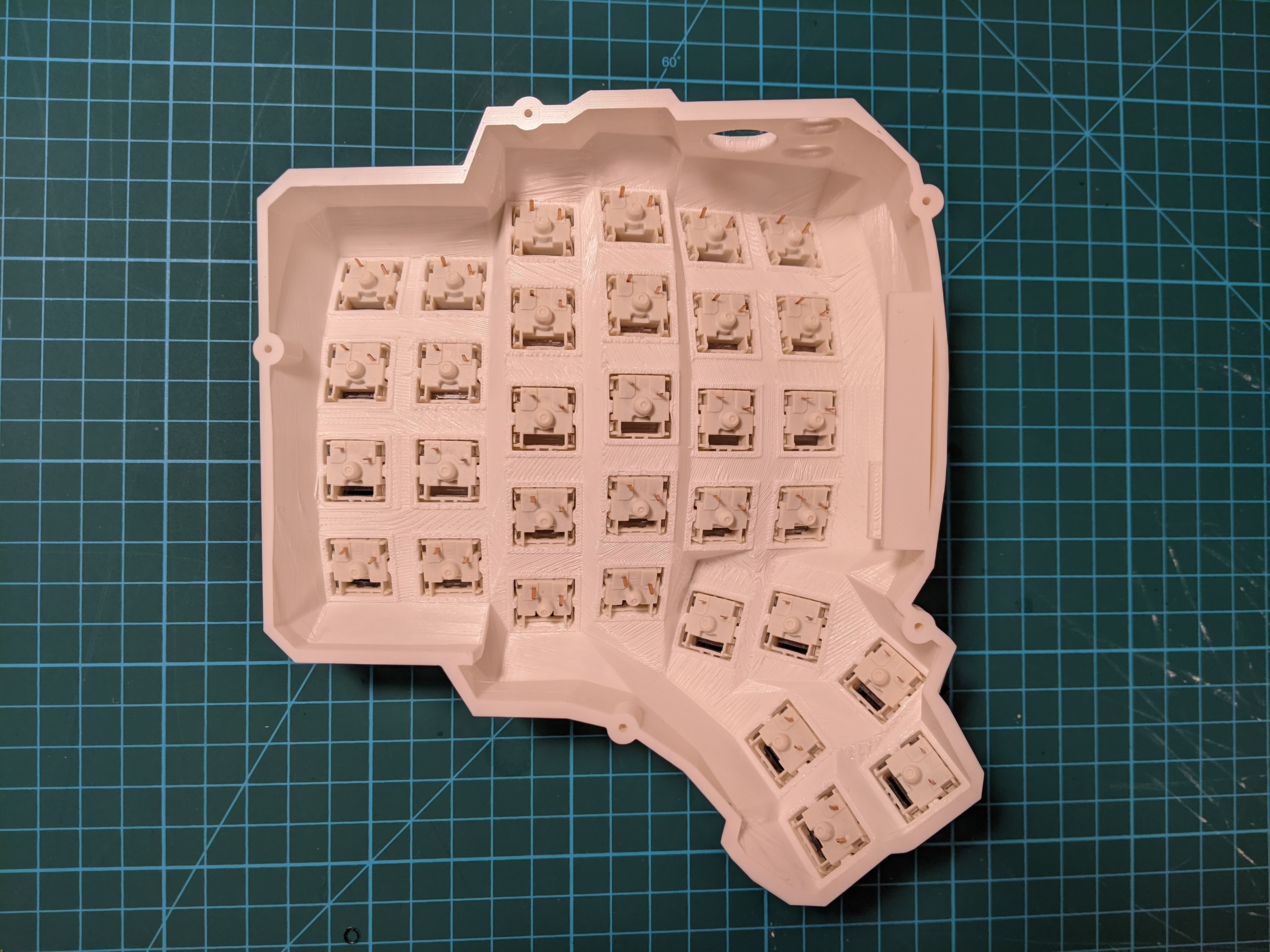
First, we put the switches into the case. They are only press-fit mounted so be careful when removing keycaps as you can easily pull the switch out along with the keycap. Here's what it looked like before any soldering:
For the rows I used a method where no additional wire is required and the diode leads are used to connect one key to the next. Pay attention to the orientation of the diodes!

Then I wired the columns (please excuse my poor soldering skills):

Then the rows and columns need to be wired to the right pins on the Arduino:

The 3.5mm socket and the reset button also need to be wired to the Arduino and the whole thing needs to be repeated for the other side:


Then we mount the USB socket, connect it to the Arduino and try to squeeze everything inside the case. In theory the case includes a holder for the Arduino board, but I ended up not using it. With all the wires the board doesn't move around too much. I put some foam between the switches and the Arduino to avoid shorts.

Before attaching the bottom plates, test the thing! Suprisingly in my case it worked the first time with no issues.
A quick note on how the two halves work together. Each half of the keyboard has an Arduino Pro Micro board that's wired to the key matrix. In theory you could just connect each half separately to the computer via USB and it would work. But then we'd end up using two USB ports just for the keyboard and we wouldn't be able to do some clever tricks with the layout that require communication between the two halves. So instead the way it works is only one half is connected to the computer through USB and the two halves are connected to each other using a serial interface - that's what the 3.5mm jacks are for (BTW, don't connect or disconnect the 3.5mm cable while the keyboard is connected over USB):

How does the Arduino know if it's the left or the right half? By default the USB cable is supposed to be connected to the left half so that's how it decides: if USB is connected, then it knows it's the left half, otherwise it's the right half. I didn't like that very much, I wanted the freedom to connect USB to any of the halves. Fortunately that variant is fully supported, you just have to store the left/right identity in EEPROM when flashing the board. To achieve that I commented out the #define MASTER_LEFT in keyboards/handwired/dactyl_manuform/5x6/keymaps/default/config.h and uncommented #define EE_HANDS. Then to flash the left half I do:
make handwired/dactyl_manuform/5x6:default:avrdude-split-left
And to flash the right part I do:
make handwired/dactyl_manuform/5x6:default:avrdude-split-right
When the software tells you to reset the board, you double tap the reset button quickly. If you don't want to mess around with compiling the firmware yourself and generally want to avoid the command line, there's this thing called the QMK Toolbox that has a nice GUI.
And now for the fun part, defining your own layout! There's an online configurator where you can define your key mapping and download a JSON configuration file. Or you can modify the keymap.c file in keyboards/handwired/dactyl_manuform/5x6/keymaps/. If you go the JSON route, just delete the keymap.c file and put a keymap.json file in the same directory. Then flash the firmware using the commands above. Or if you're using the QMK Toolbox, the online generator can compile the thing for you.
I hope this quick report helps someone, have fun if you decide to build one yourself. I really think it's a nice project!
