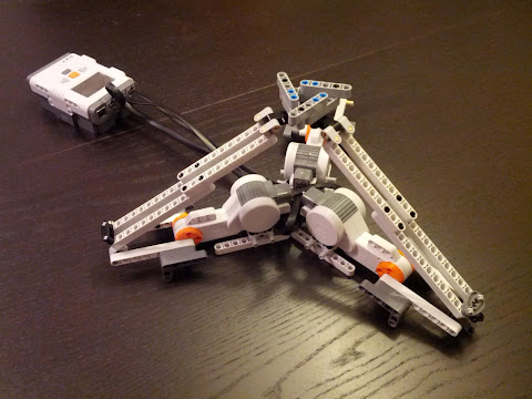
2012-12-11

Face tracking robot

Android 4.0 introduced an API for face detection. It's really simple to use, you only have to set up a listener and it gets called each time a face is detected in the frame captured by the camera. I used it to make a Lego Mindstorms NXT robot that turns to look at you as you move around. Here's what it looks like:


The way it works is there's an application on the phone that checks if a face is detected. Then it communicates with the robot over Bluetooth and tells it to turn left or right, depending on the position of the face in the frame. Here's the application's source code if you want to take a look. I don't have building plans for the robot itself, but any robot with tank-like steering would work.

A cool way to demo this robot would be to use it for video chats or Google+ hangouts, but I don't think there's a way for two different applications to access the camera at the same time, so the face tracking functionality would have to be integrated into a video chat app. (Or I guess I could put a second phone on the robot.)


2012-10-21

Fridge temperature monitoring with Raspberry Pi

Since I've discovered that it's relatively easy to access Raspberry Pi's GPIO pins, I'm constantly looking for stuff to connect to it. Fortunately the Internet is full of them.

One of Raspberry Pi's limitations (compared to, say, an Arduino) is that it doesn't have analog pins, only digital ones. So to connect a sensor with analog output, you have to go through an analog-to-digital converter (ADC). The fine folks at Adafruit have written a tutorial on how to talk to an MCP3008 ADC from a Raspberry Pi to read the state of a potentiometer. I swapped the potentiometer for a TMP36 temperature sensor and now my Raspberry Pi knows what the temperature is.

Here's a nice looking diagram of how the connections go:


And here's a considerably more messy real-life shot:


I monitored the temperature in my room for some time and decided that it was boring. So then I put my new creation in the fridge to see how cold it is in there. Initially I wanted to put just the sensor in and keep the Raspberry Pi outside, but with all the cables going from the Pi to the breadboard, it was easier to just put everything inside with only the power cable going out. The Pi didn't mind the low temperature and I hope the small amount of heat it produces didn't affect the fridge and the measurement. And if you ever wondered whether wifi would work from inside a fridge, I'm happy to report that it works just fine.

Here's what it looked like inside my otherwise mostly empty fridge:


And here are the results:


(I averaged the data a bit, because the readings from the sensor were pretty noisy.)

It turns out that the temperature inside my fridge varies quite a bit, from around 3 °C to around 8 °C. The compressor runs for about 37% of the time (though that number probably depends on outside temperature and possibly the contents of the fridge).

Here's the script I used to read the temperature from the sensor, but it's mostly identical to the one in Adafruit's tutorial. One interesting thing about it is that it uses what's called a "bit banging" SPI implementation (the Raspberry Pi also has hardware SPI and we could use that just as well).

2012-08-26

Raspberry Pi controlled lamp

I'm a software guy and I'm scared of electronics. At the same time I find it exciting when software actually does something in the real world. (That's why I love Lego Mindstorms.) Home automation is my lifelong dream. I'd like to be able to use my computer to turn the lights on and off, roll up the window blinds and remotely control everything else that can be controlled.

That dream will have to wait, but today I used my Raspberry Pi to make a small proof of concept.


One of the many cool things about the Raspberry Pi is that it has some general purpose I/O pins exposed that can be used to communicate with the outside world using various protocols. The simplest thing you can do is to set a single pin to a high or low state. When combined with something called a relay, that is enough to control an electrical device plugged into a wall socket (or at least to turn it on and off). I used this relay from Seeedstudio. The relay has three pins (actually four, but one is unused), labeled VCC, GND and SIG. I connected VCC to the 5V pin on the Pi and GND to the ground pin. The SIG pin must be connected to one of several GPIO pins available. You can find a detailed description of Raspberry Pi's GPIO pins on the wiki. I connected the SIG pin from the relay to GPIO18, which is the sixth pin from the left in the top row.

Then I butchered a power strip. I removed the insulation from a segment of the cable, cut one of the cables inside, stripped some insulation from the ends and put them into the screw terminal on the relay. This is the part I was most uneasy about. You should obviously exercise caution when working with stuff that will be connected to mains voltage (extra caution when it actually is connected).

With everything attached, the only part remaining is software. The GPIO pins can be controlled through special files in the /sys filesystem, but I used a library called WiringPi. It includes the gpio command line tool, which makes working with GPIO pins easy.

First you have to configure the pin for output:

gpio export 18 out

Then you can set the state to high with:

gpio -g write 18 1

And to low with:

gpio -g write 18 0

Thus switching the relay on and off. I wrapped those commands in some trivial CGI scripts for the purpose of demonstration and controlled the lamp via a web browser.

2012-08-21

NXT delta robot

A delta robot is a robot with three motors placed on a triangular base, connected to a smaller triangular platform through three arms (the second platform is called the end effector, because it's the part that actually does stuff). The arms have universal joints in them and work as parallelograms. Because of that, the end effector's movement is restricted to just X,Y,Z translations, it doesn't rotate and stays parallel to the base. Because of their speed and precision, delta robots are widely used in the packaging industry and other places.

They're also the kind of thing that you look at and immediately think hey, I bet I could recreate that with Lego Mindstorms!


To make the robot work, we have to take the desired position of the end effector and translate it to angles to which the three arms must be rotated by the motors (fancy term for that is inverse kinematics). It involves some geometry, but luckily for us a man named Maxim Zavatsky worked it all out and posted a nice tutorial here. The program that controls my robot (which you can see here) is mostly a copy & paste of his code.

When making this robot, I found out that even though the NXT motors have encoders that tell you their rotations with degree accuracy, it's not very easy to precisely reach a certain angle on the motor. Setting up a gear reduction would help with the precision, but the Mindstorms set doesn't come with enough gears for three arms. I ended up using absolute position regulation from the enhanced NBC/NXC firmware (PosRegEnable() and PosRegSetAngle() functions). Since the PosRegSetAngle() call is non-blocking (it returns immediately and the position regulation happens in the background), it would be good to have a way of knowing when the motor has reached its set point. One solution that comes to mind is to keep watching the motor's position and when it stops changing assume that it is as close to the desired angle as it's going to get. Right now I'm using hard-coded Wait() calls, which is obviously not optimal.

My robot doesn't actually do anything (except move), but it would be interesting to attach a pen to it and make it into a drawbot. For that I'd have to somehow mount it upside down and probably work on making it a little stiffer (right now it's pretty wobbly). Another thing to try would be to reverse the calculations and turn the robot into a 3D input device (you would move the end effector by hand, read the angles from the motors, translate those into X,Y,Z and send the data to a computer).

Here's an album with some pictures of the robot.

Subway buddies

Have you ever wondered if you're meeting the same people every day on your daily commute? Over half a million people ride the Warsaw Metro daily, but if I arrive at the station at roughly the same time every day, surely there must be others with similar schedules? But even after almost a year of taking the same route, I couldn't recognize any familiar faces. So I decided it was time for a more scientific approach.

A surprisingly large number of people leave their phone's Bluetooth in discoverable state (I find it strange, because on most phones I've seen the default behavior is only to become discoverable for 120 seconds or so when pairing). I thought if I scanned for Bluetooth devices every time I rode the subway and saved the results, I could then check if I ever saw the same device on different days. So that's what I did, I made an application for my phone that does a Bluetooth scan and logs all devices it sees in a SQLite database. That was not ideal yet, because I still had to trigger the scan manually every time (I didn't want to keep scanning all the time, because that would quickly drain the battery and also I'd get a lot of false positives from my neighbors, coworkers etc.). Happily, there is a solution. Living in a city, just about the only time I lose cell phone signal is when I get on the subway. So that's a good condition to wait for to trigger the scan (there will be occasional false positives, but they don't bother us much). Obviously, this only works if your commute involves riding the subway and not, say, a bus.

Here's the source code of the application if you'd like to play with it.

So are there any strangers that happen to commute at the same time I do? After just two weeks of the experiment, with the help of a SQL query:

select addr, count(*), max(sightingtime)-min(sightingtime) y, group_concat(sightingtime) from sighting group by addr having y > 3600 order by y desc;

I found two persons that I shared a subway ride with on two different days. Unfortunately I can't really say much about them, except for the fact that one of them had an LG phone and the other a Samsung.

2012-02-21

Electricity meter fun

At the place I live, the electricity meter looks like this:


The fancy display shows total kilowatt hours and maximum power consumption, but it doesn't show current consumption. Instead it has this blinking red light - the faster it blinks, the higher the power consumption. But to get the actual figure, I'd have to count how many times it blinked, measure the time and then do some arithmetic. And that would be pedestrian. Instead I wrote an application for my phone that does the measurements (with the phone's camera) and displays the current power consumption:


Here's the source code if anyone's interested.