2022-07-27

DIY Surface Dial

Microsoft's Surface line of hardware has some nice computers and accessories. Among the accessories there's the Surface Dial - a Bluetooth knob that can do things like volume control, scrolling, undo/redo and some other functions in certain applications, mostly artist-oriented. For some reason the physical form of the Surface Dial appeals to me, but since its price is not exactly in the impulse buy territory and I don't have a practical need for it, I never got one. But now I have made my own version of it. It's not as nice as the real one and it's missing some of the functionality, but it really does work as a Surface Dial in the software that supports it.

There are two aspects to this device, making the physical hardware and programming it so that Windows recognizes it as a Surface Dial.

From the hardware perspective, we need two things - a way of detecting the dial's rotation and a button. On the real Surface Dial the entire knob works as a button, but in my version, there's a separate button in the middle, made using a mechanical keyboard switch. As for the dial itself, instead of using an off-the-shelf rotary encoder, I made my own using small neodymium magnets and two Hall effect sensors. Its principle of operation is the same as with other incremental encoders, the sensors are oriented so that their signals have a phase difference. In theory we could get better resolution by using the full resolution of the sensors' output, instead of treating them as binary, but I haven't done that. The resolution I got is determined by the number of magnets (48).

I designed the case for the device in Fusion 360 and 3D printed it. The dial sits on a 6806 ZZ bearing and has a very satisfying feel. Here's what it looked like during assembly.

For the microcontroller I chose the Adafruit QT Py RP2040, it's small and uses the RP2040 chip from Raspberry Pi (it has a similar form factor to Seeed Studio's XIAO RP2040).

Since we're talking about Microsoft, I half-expected the Surface Dial's protocol to be some proprietary nonsense that would require reverse engineering to replicate. Imagine my surprise when I found out that it's actually standard HID and there's proper documentation for it. All you have to do is put the right stuff in the HID report descriptor and it works similarly to a regular USB mouse or keyboard.

I put all the code and 3D-printable files on GitHub, along with a list of components used and instructions how to put them together.

2022-07-09

Two mice, two cursors

I always thought that when you connect two mice to a computer, there should be two mouse cursors, one for each mouse. Unfortunately that's not really how it works on modern operating systems, at least not by default. Software add-ons exist that draw a second cursor for the second mouse (and also perform some tricks to make button clicks work as expected). I'm sure they work fine, but I came up with a pure hardware solution to the problem that requires no special software running on the host. Here's a video demonstrating this solution.

What you can see here is two mice, connected through a USB hub to an Arduino Leonardo with a USB Host Shield. The mice are wireless, but they use 2.4 GHz USB receivers so they're effectively USB devices. The Arduino is connected to the computer and acts as a USB mouse.

The Arduino reads inputs from the two mice, does its magic, and sends the resulting inputs to the computer. What's the trick that makes the computer display two cursors? If you look closely, you'll notice that the two cursors flicker a bit. That's because they're not really two cursors, instead it's just the one normal cursor oscillating quickly between two positions on the screen, appearing as two due to persistence of vision. The Arduino keeps track of the X/Y positions of both cursors and updates them based on the inputs received from each mouse. Then it alternates between the two causing the illusion of two cursors. To be able to do that it uses absolute cursor positioning, unlike a regular mouse, which only sends the X/Y deltas and doesn't know where on the screen the cursor is at any moment. (I have previously used absolute cursor positioning for both good and evil.)

One remaining problem is what to do when you click a button on one of the mice. The user will naturally expect for the click to happen at the screen position of the cursor corresponding to that mouse. So we can't keep alternating between the two cursors. For as long as the button is pressed, we only send the cursor position of the mouse that's doing the clicking. This means that the second cursor disappears for a brief moment, but the clicks work as expected.

If you want to play around with it, I posted the source code on GitHub. It uses the standard USB HID protocol and works with Windows, Linux and Mac, without any additional software needed on the computer.

2022-07-07

Razer Raion padhack

One of the problems when making a custom fightstick (arcade controller for fighting games) is modern console compatibility. While it was easy to make an Arduino or similar board work as a USB controller for the PS3, unfortunately it is no longer the case with the PS4 and PS5. Only licensed controllers work with them due to restrictions introduced by Sony. Every licensed controller has a private key embedded in it that allows it to perform some kind of authentication when connected to a console. One solution to this problem is a practice known as padhacking: taking the insides of an existing licensed controller and transplanting them into a different enclosure, for example a fightstick-shaped one, carefully soldering wires between buttons and the right places on the donor PCB.

In theory you can use any controller for this, like a DualShock 4 or a DualSense, but it makes sense to choose one that will be relatively cheap to obtain and also easy to solder to. One such controller is the Razer Raion. It was originally released for the PS4, but since it qualifies as a "specialty peripheral", it also works in PS5 games. I got one and made a mixbox-layout fightstick using its PCB.

First I had to figure out where the solder points that I need are on the PCB. Fortunately I found this helpful tweet and with this information it was a fairly straightforward job.

The rest of the fightstick was similar to what I've done previously, in fact I just modified one of the designs to accomodate the Raion PCB. Here's what it looks like inside. As you can see it uses common ground.

One thing to keep in mind when converting a controller like this is the matter of SOCD cleaning - what happens when you press opposing direction buttons at the same time? Most traditional controllers don't have to worry about this because it's physically impossible to simultanously trigger opposing directions on them. But when you make a stick that has separate buttons for up, down, left and right, that can be pressed independently, it's something you have to start thinking about. In case of the Razer Raion, it uses a scheme called first input priority, meaning that if you press and hold left, then press and hold right, it will keep sending left. When you release left, then it will start sending right. If I didn't like this, I'd have to add an external SOCD cleaner between the buttons and the Raion PCB.

I posted the 3D-printable models for this stick on Printables. It uses Kailh low profile (choc v1) mechanical keyboard switches for the buttons. Here's what the final result looks like.

2022-07-06

Flatbox

Having previously made some 3D printed fightsticks (arcade controllers for fighting games) that were just plastic boxes with holes for arcade buttons or mechanical keyboard switches, I started thinking, could I make one that's even thinner? On my previous designs I just soldered wires to the keyboard switches, but they're really intended to be soldered onto a printed circuit board. Using a PCB instead of the wire spaghetti inside the case seemed like a good way to shave a few millimeters off. And it turns out there are companies in China that will manufacture a custom PCB for you for very reasonable prices. And thus the Flatbox was born. I ended up making four revisions of it.

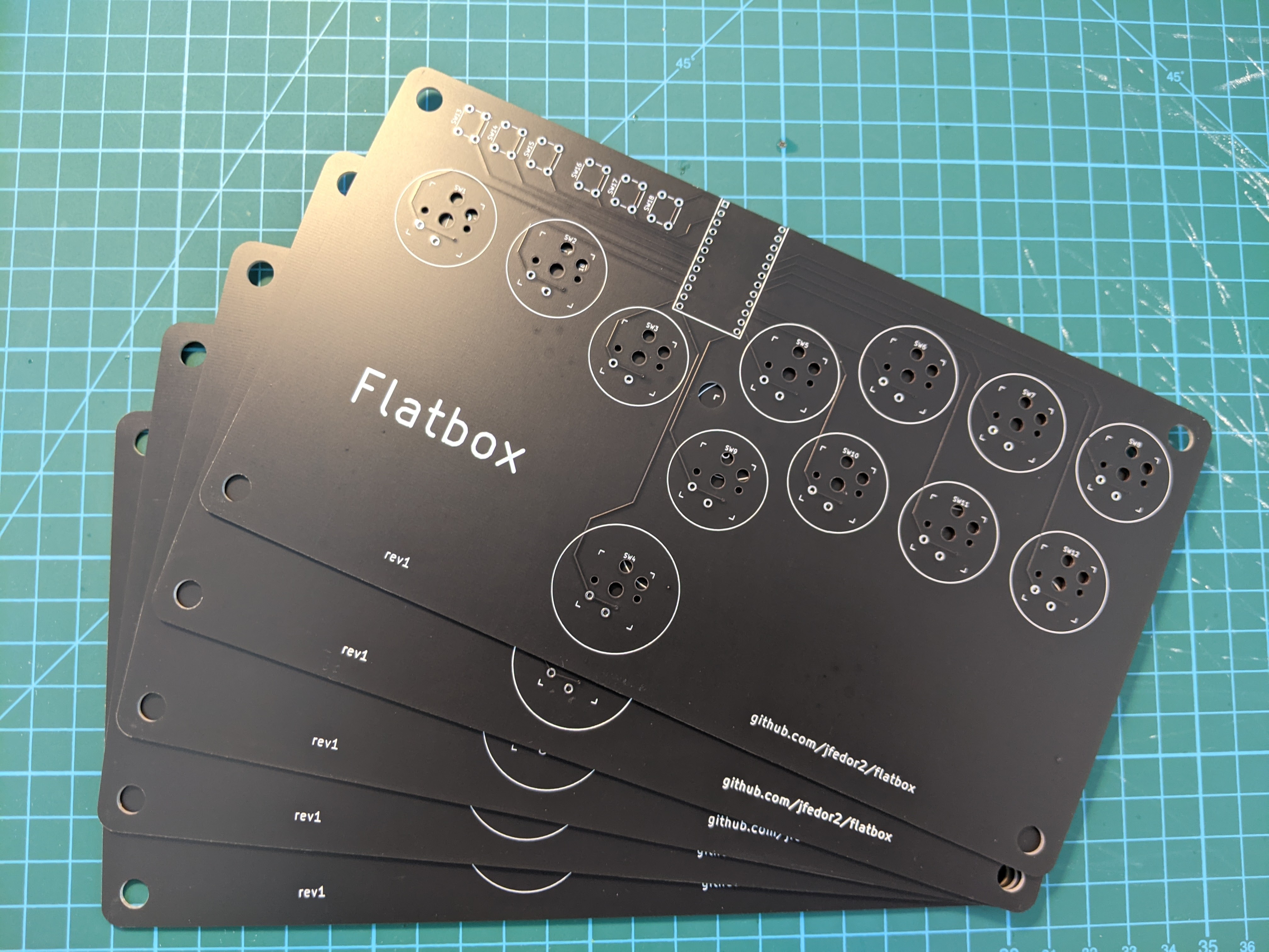
Up to this point I was using Arduino Pro Micros as the brains of my fightsticks, so it seemed natural to start with a PCB that I could solder a Pro Micro onto. The PCB would just serve as a connection between the Arduino's pins and the keyboard switches (I used Kailh choc v1 low profile switches). I designed my board in KiCAD, arranged the switch footprints in a hitbox-style layout, generated the Gerber files and sent them off to JLCPCB for manufacturing. After some days I was excited to receive a package with my boards inside.

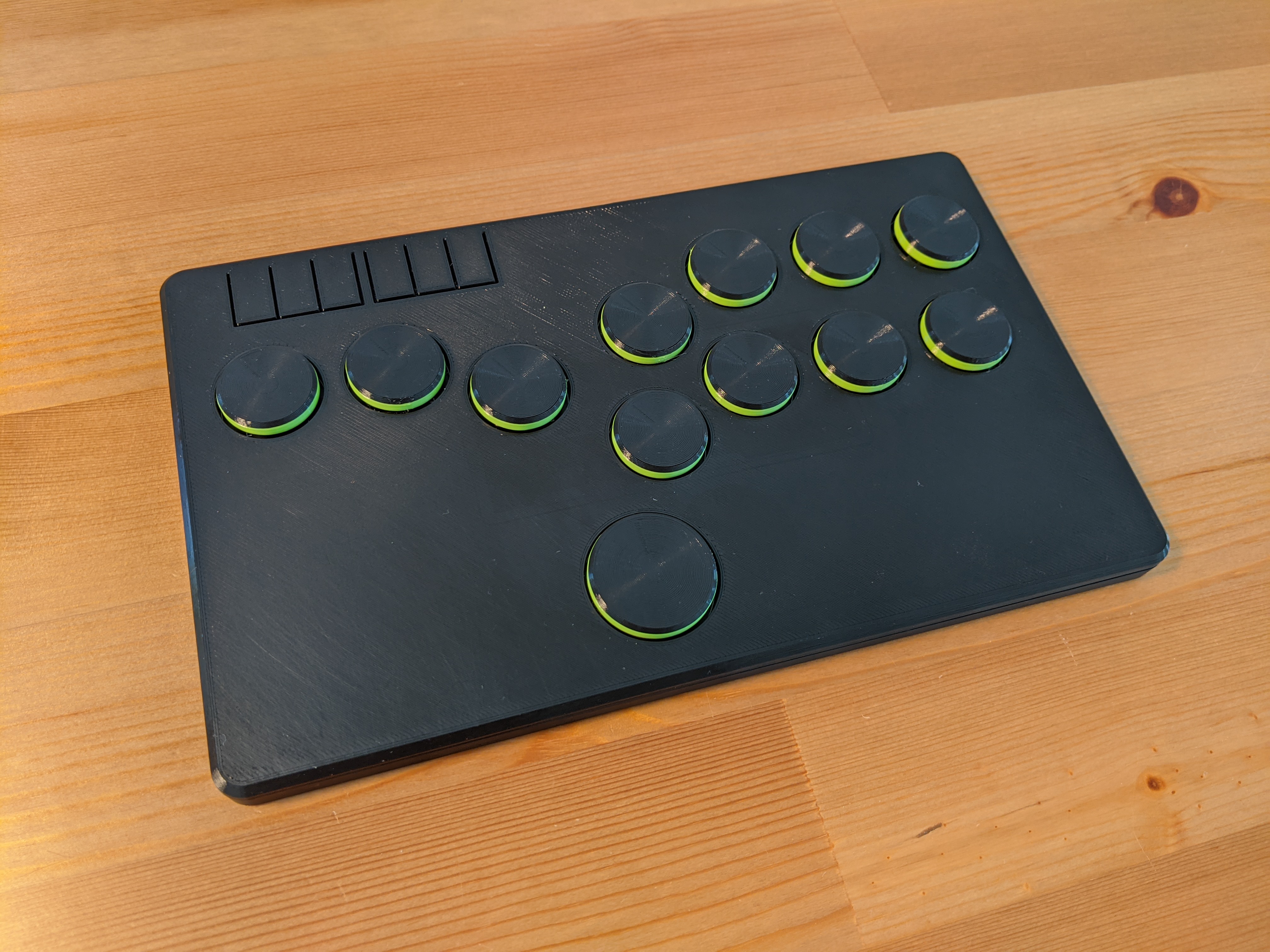
I've never done anything like this before so I wasn't sure if the boards would even work at all. I'm used to prototyping on breadboards, if you make a wrong connection there it's usually not a big deal and it's a matter of seconds to correct it. Here if I made a mistake, not only would it cost money, but I'd also have to wait a week or two for another package from China. But fortunately everything worked great! I quickly designed and 3D printed an enclosure for it. I was very pleased with the result, just 10 millimeters thick!

I was encouraged by this initial success, but I thought having to solder an Arduino board onto my PCB wasn't very elegant. Surely an Arduino is just another PCB and I should be able to include the microcontroller and all the other necessary components on my PCB and eliminate the need for an additional board. That's what I did for revision 2. I designed the board to use SMD (surface mount) components for everything except the keyboard switches and option buttons. I would probably not be able to solder them manually, but fortunately JLCPCB will happily do the assembly for you, you just have to provide two more files in addition to the Gerbers (list of components and their placement on the board). This time I was even more afraid that it wouldn't work at all, because there was a lot more I could mess up, but surprisingly the whole thing worked on the first attempt. Because it uses the same chip as the Pro Micro (ATmega32U4), I was able to use the same firmware. I was very happy, because even though manufacturing the boards was a little more expensive, it was suddenly starting to look somewhat like a real product.

Speaking of firmware, while it's easy to make a USB HID device that works with a PC or a PS3, it is unfortunately not the case with more modern consoles. From the PS4 onwards, Sony started restricting their systems to only work with licensed controllers. Each licensed pad or stick has some special chip with a private key inside it that lets it authenticate to the console. And DIY-ers are out of luck. Except you can buy PCBs that somehow get around Sony's restrictions (I don't know how they do it). I wanted a version of the Flatbox that was compatible with the PS4 so for revision 3 I went back to the idea of soldering an add-on board onto the main PCB. I chose the Brook PS3/PS4 board because of its small size. The only SMD components on the main board are the USB port and the two resistors that it requires.

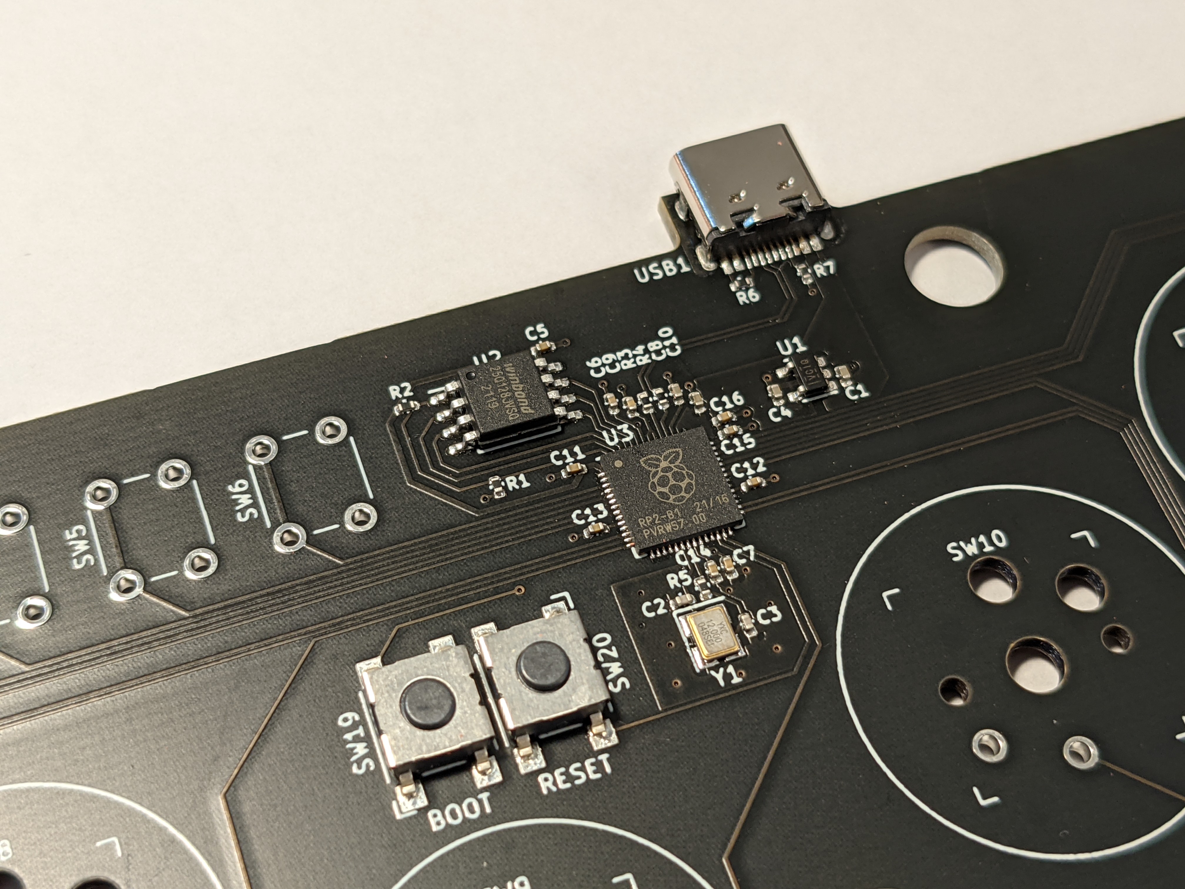
The fourth and final revision of the Flatbox again has all the components on the main PCB and doesn't require an add-on board. It is similar to revision 2, but instead of the ATmega32U4 chip it uses Raspberry Pi's RP2040. It is the revision I like best, even though it's not compatible with the PS4 or the PS5.

All the files needed to make your own Flatbox are on GitHub, including KiCAD projects for the PCBs, 3D-printable models for the case and source code for the firmware.

2022-07-04

Fightsticks

Fighting games like Virtua Fighter, Tekken or Street Fighter originated at the arcades and have traditionally been played on cabinets with heavy duty joysticks and buttons. Even though they're mostly played on consoles and PCs these days, many players use arcade sticks modeled after the arcade cabinets, either because they consider them superior to controllers or simply because they enjoy their old school look and feel.

Arcade stick parts like buttons and joysticks can be bought separately so it's fairly easy to make your own stick. All that's needed is some kind of a box and a microcontroller that will read the state of the buttons and send the appropriate inputs to the PC or console. Not suprisingly, there's a thriving DIY community of fightstick makers.

I designed a few arcade stick cases meant to be 3D printed. The ones shown below all use an Arduino Pro Micro as the brains, running this firmware, compatible with PC and PlayStation 3. If you like any of them and want to try making your own, I've posted all the 3D-printable models on Printables, along with more pictures and details on how to make them.

The first one uses the most classic layout, with a Sanwa JLF joystick, 30 mm action buttons and 24 mm option buttons at the back. I made versions with 6 and 8 actions buttons.

The traditional appeal of arcade sticks doesn't mean that things are standing still. Some new stick layouts have emerged over the years, the most popular of them probably being the hitbox layout, which ditches the actual joystick and instead uses four buttons for the direction inputs. The large button at the bottom is the jump button and it's meant to be operated by either your left or right thumb. This layout seems best suited for 2D games like Street Fighter. You can see my take on this control scheme below.

Another layout that uses buttons instead of the joystick is the mixbox layout. It uses keyboard keys in a more familiar WASD shape for the direction inputs. In my opinion it's better for 3D fighters like Virtua Fighter and Tekken than the hitbox layout. Here's my version.

In addition to new stick layouts, people have also started putting alternative parts in their sticks. One move that's obvious in retrospect is to try using mechanical keyboard switches instead of the traditional arcade buttons. There are many different keyboard switches to choose from and they also allow the fightstick case to be much slimmer. Here's my attempt at a hitbox-layout controller that uses Kailh low profile keyboard switches and is just 14 mm thick (I call it the Slimbox).

Similarly, here's a mixbox-layout version of the same idea (Slimbox M).

2021-01-27

Bluetooth trackball Mark II

I made a Bluetooth trackball in which all the electronics are inside the ball. The ball is the entire trackball. Here it is in action:

Inside the ball there's a microcontroller and a set of sensors that together with some clever algorithms allow the microcontroller to know the ball's absolute orientation in 3D. When the ball is rotated, it sends the appropriate commands to the computer over Bluetooth to move the mouse cursor. Oh, and the keyboard in the video is a completely separate USB device, it's only used for mouse clicks and doesn't interact with the ball in any way.

This is actually the second iteration of the project. While I was very proud of my previous attempt, it had some undeniable shortcomings and was generally a proof-of-concept quality device. This new version improves upon it in many regards, to the point where I think it could possibly be used on a day to day basis as a replacement for your regular mouse. Specific features include:

  • an nRF52840 chip along with LSM6DS33 accelerometer/gyroscope and LIS3MDL magnetometer
  • a wirelessly rechargeable 500 mAh battery
  • battery level reporting over Bluetooth
  • more robust "up" calibration
  • fully sealed construction allowing for smooth rolling of the ball

I used Adafruit's Feather nRF52840 Sense, it has all the necessary sensors onboard. The other components are a lipo battery, a wireless charging coil and two reed switches, one of which is connected to the board's "En" pin, allowing us to turn the device off with an external magnet, the other is connected to a GPIO pin and is used to trigger the "up" calibration.

The ball is 65 mm in diameter and is made of two 3D printed halves. After putting the electronics inside I glued the two halves together and smoothed the surface by progressing through increasingly finer grits of sandpaper. It rolls pretty smoothly on 2.5 mm zirconium oxide bearing balls, though it's still admittedly not as smooth as a real trackball. I made a few bases in various shapes for the ball to roll on, they are just pieces of 3D printed plastic and don't have any electronics in them.

To charge the battery inside the ball I also made a special base that has a wireless charging coil inside and is powered with USB (or any 5V source). It also has a strategically placed magnet that can be used to trigger one of the two reed switches inside the ball, one will turn the device off, the other allows for setting the logical "up" directon of the trackball (by itself the trackball doesn't know which direction should move the mouse cursor up, so you can set it by putting a magnet near one of the reed switches and rotating the ball around the vertical axis).

The Arduino code and 3D models are on GitHub.

2020-11-06

Dactyl Manuform build log

I made an ergonomic split keyboard using the Dactyl Manuform design, specifically the 5x6 version. I'm going to describe the process in the hope that it will be useful to someone considering making one. Here's what the final product looks like:

The Dactyl Manuform, made by Tom Short, is a modification of the original Dactyl keyboard design by Matthew Adereth. Matthew has given an entertaining talk on his design process. It won't really help with building the keyboard, but it has some nice bits on keyboard history in general.

The keyboard is controlled by an Arduino Pro Micro (one in each half) which is running the QMK firmware. This firmware is used by many keyboards, both hand-made and mass-produced and it has several useful features and allows you to customize the keyboard to a much greater extent compared to what's possible on a normal one.

Let's get to it. First we need to decide on the general shape of the keyboard and 3D print the case (or have someone 3D print it for us). I went with 5x6, meaning 5 rows and 6 columns of keys, which translates to having a row for the 0-9 keys, but not for the function keys. The fifth row only has two keys and there's also a 6-key thumb cluster. The 3D models are generated by a Clojure program that outputs a .scad file that is then converted to STL using OpenSCAD. Things like the number of rows and columns and the angles are all configurable in the Clojure code. If you don't want to mess with Clojure, there's an online generator that lets you customize some things and gives you a .scad file.

Here's what it looked like after printing in my case:

I've made some modifications to the design, fixing some issues and changing the holes for the ports to circular ones (so that they can easily be used with panel-mount sockets). I also added a hole for a reset button, which is useful when programming the thing. You can get my STL files on Thingiverse. People often cut the bottom plate from acrylic or even metal, but I just 3D printed it like the rest of the case. I also didn't use heat set inserts and just went with wood screws. Oh, and I really recommend using Cura with tree supports when printing the case. Normally I use PrusaSlicer for everything, but in this case the supports it generated were practically impossible to remove. Printing each half took about 20 hours on my Prusa MK3S.

In addition to the case, here are the parts that I used:

  • Arduino Pro Micro (2x)
  • Gateron Brown switches (64x)
  • DSA profile keycaps (60x 1u and 4x 1.5u)
  • 1N4148 diodes (64x)
  • panel-mount micro USB socket (2x)
  • panel-mount 3.5mm TRS socket (2x)
  • panel-mount momentary switch (2x)
  • some hookup wire, 24 AWG
  • 3x10mm wood screws for attaching the bottom plate (10x)

Then we need to actually wire the thing. To avoid having to use a separate wire going to the controller from every key, a matrix circuit is used, meaning the keys are arranged into rows and columns and there's a diode connected to every key. There's a wiring diagram on Tom Short's repository, but it's somewhat confusingly described as "alternative". The alternative one is the one you want.

First, we put the switches into the case. They are only press-fit mounted so be careful when removing keycaps as you can easily pull the switch out along with the keycap. Here's what it looked like before any soldering:

For the rows I used a method where no additional wire is required and the diode leads are used to connect one key to the next. Pay attention to the orientation of the diodes!

Then I wired the columns (please excuse my poor soldering skills):

Then the rows and columns need to be wired to the right pins on the Arduino:

The 3.5mm socket and the reset button also need to be wired to the Arduino and the whole thing needs to be repeated for the other side:

Then we mount the USB socket, connect it to the Arduino and try to squeeze everything inside the case. In theory the case includes a holder for the Arduino board, but I ended up not using it. With all the wires the board doesn't move around too much. I put some foam between the switches and the Arduino to avoid shorts.

Before attaching the bottom plates, test the thing! Suprisingly in my case it worked the first time with no issues.

A quick note on how the two halves work together. Each half of the keyboard has an Arduino Pro Micro board that's wired to the key matrix. In theory you could just connect each half separately to the computer via USB and it would work. But then we'd end up using two USB ports just for the keyboard and we wouldn't be able to do some clever tricks with the layout that require communication between the two halves. So instead the way it works is only one half is connected to the computer through USB and the two halves are connected to each other using a serial interface - that's what the 3.5mm jacks are for (BTW, don't connect or disconnect the 3.5mm cable while the keyboard is connected over USB):

How does the Arduino know if it's the left or the right half? By default the USB cable is supposed to be connected to the left half so that's how it decides: if USB is connected, then it knows it's the left half, otherwise it's the right half. I didn't like that very much, I wanted the freedom to connect USB to any of the halves. Fortunately that variant is fully supported, you just have to store the left/right identity in EEPROM when flashing the board. To achieve that I commented out the #define MASTER_LEFT in keyboards/handwired/dactyl_manuform/5x6/keymaps/default/config.h and uncommented #define EE_HANDS. Then to flash the left half I do:

make handwired/dactyl_manuform/5x6:default:avrdude-split-left

And to flash the right part I do:

make handwired/dactyl_manuform/5x6:default:avrdude-split-right

When the software tells you to reset the board, you double tap the reset button quickly. If you don't want to mess around with compiling the firmware yourself and generally want to avoid the command line, there's this thing called the QMK Toolbox that has a nice GUI.

And now for the fun part, defining your own layout! There's an online configurator where you can define your key mapping and download a JSON configuration file. Or you can modify the keymap.c file in keyboards/handwired/dactyl_manuform/5x6/keymaps/. If you go the JSON route, just delete the keymap.c file and put a keymap.json file in the same directory. Then flash the firmware using the commands above. Or if you're using the QMK Toolbox, the online generator can compile the thing for you.

I hope this quick report helps someone, have fun if you decide to build one yourself. I really think it's a nice project!