Showing posts with label rp2040. Show all posts

2022-07-27

DIY Surface Dial

Microsoft's Surface line of hardware has some nice computers and accessories. Among the accessories there's the Surface Dial - a Bluetooth knob that can do things like volume control, scrolling, undo/redo and some other functions in certain applications, mostly artist-oriented. For some reason the physical form of the Surface Dial appeals to me, but since its price is not exactly in the impulse buy territory and I don't have a practical need for it, I never got one. But now I have made my own version of it. It's not as nice as the real one and it's missing some of the functionality, but it really does work as a Surface Dial in the software that supports it.

There are two aspects to this device, making the physical hardware and programming it so that Windows recognizes it as a Surface Dial.

From the hardware perspective, we need two things - a way of detecting the dial's rotation and a button. On the real Surface Dial the entire knob works as a button, but in my version, there's a separate button in the middle, made using a mechanical keyboard switch. As for the dial itself, instead of using an off-the-shelf rotary encoder, I made my own using small neodymium magnets and two Hall effect sensors. Its principle of operation is the same as with other incremental encoders, the sensors are oriented so that their signals have a phase difference. In theory we could get better resolution by using the full resolution of the sensors' output, instead of treating them as binary, but I haven't done that. The resolution I got is determined by the number of magnets (48).

I designed the case for the device in Fusion 360 and 3D printed it. The dial sits on a 6806 ZZ bearing and has a very satisfying feel. Here's what it looked like during assembly.

For the microcontroller I chose the Adafruit QT Py RP2040, it's small and uses the RP2040 chip from Raspberry Pi (it has a similar form factor to Seeed Studio's XIAO RP2040).

Since we're talking about Microsoft, I half-expected the Surface Dial's protocol to be some proprietary nonsense that would require reverse engineering to replicate. Imagine my surprise when I found out that it's actually standard HID and there's proper documentation for it. All you have to do is put the right stuff in the HID report descriptor and it works similarly to a regular USB mouse or keyboard.

I put all the code and 3D-printable files on GitHub, along with a list of components used and instructions how to put them together.

2022-07-06

Flatbox

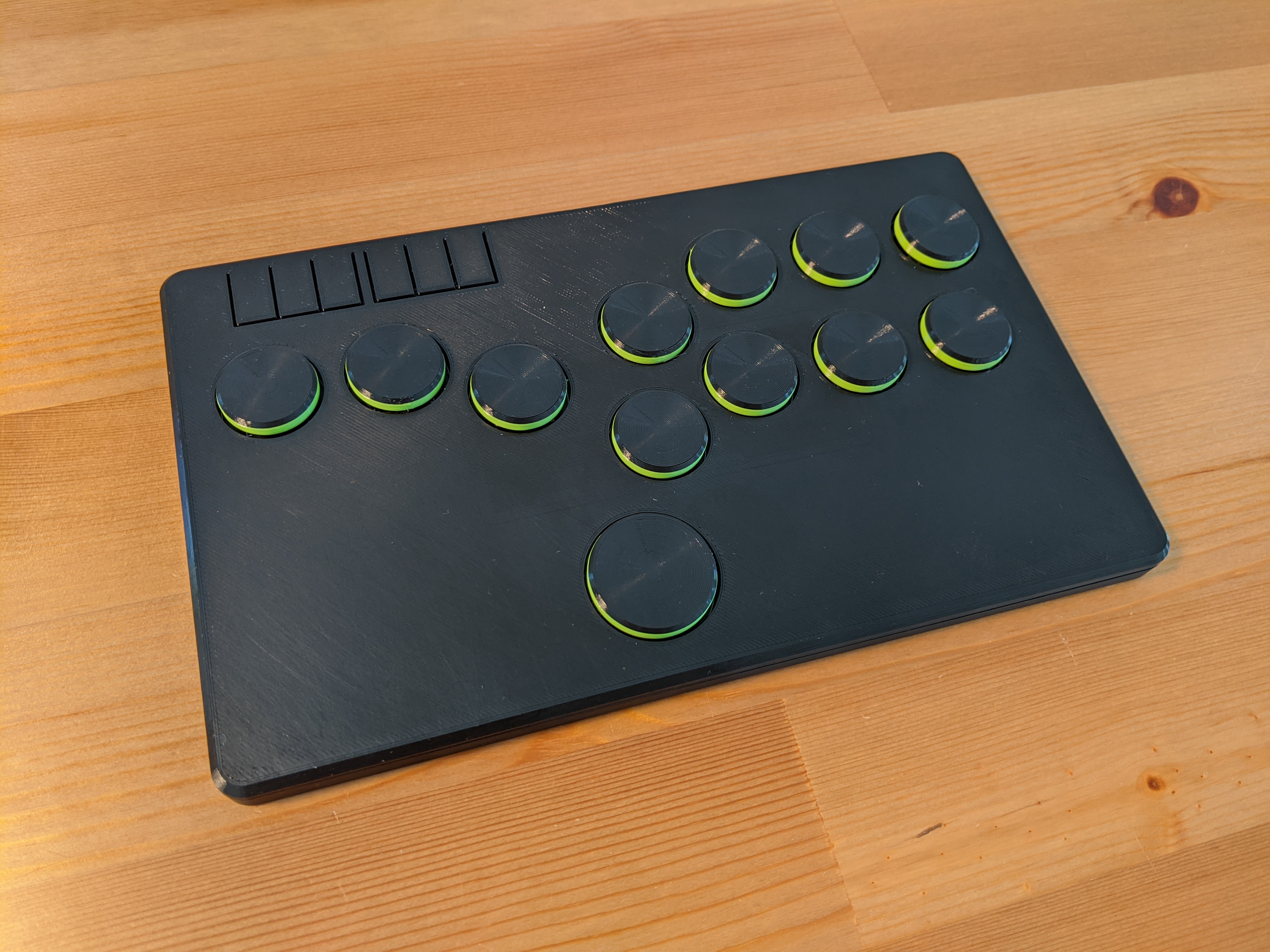
Having previously made some 3D printed fightsticks (arcade controllers for fighting games) that were just plastic boxes with holes for arcade buttons or mechanical keyboard switches, I started thinking, could I make one that's even thinner? On my previous designs I just soldered wires to the keyboard switches, but they're really intended to be soldered onto a printed circuit board. Using a PCB instead of the wire spaghetti inside the case seemed like a good way to shave a few millimeters off. And it turns out there are companies in China that will manufacture a custom PCB for you for very reasonable prices. And thus the Flatbox was born. I ended up making four revisions of it.

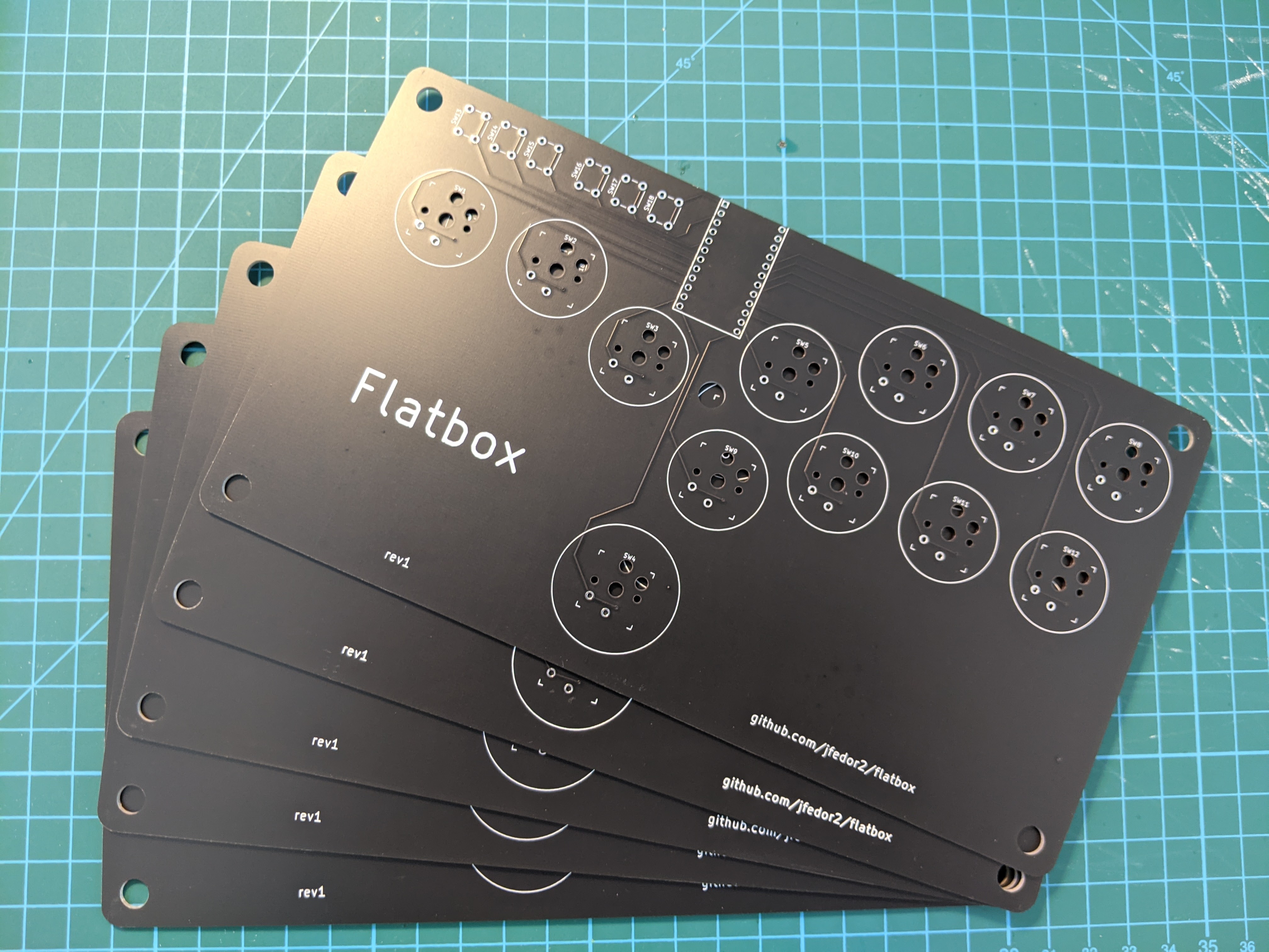
Up to this point I was using Arduino Pro Micros as the brains of my fightsticks, so it seemed natural to start with a PCB that I could solder a Pro Micro onto. The PCB would just serve as a connection between the Arduino's pins and the keyboard switches (I used Kailh choc v1 low profile switches). I designed my board in KiCAD, arranged the switch footprints in a hitbox-style layout, generated the Gerber files and sent them off to JLCPCB for manufacturing. After some days I was excited to receive a package with my boards inside.

I've never done anything like this before so I wasn't sure if the boards would even work at all. I'm used to prototyping on breadboards, if you make a wrong connection there it's usually not a big deal and it's a matter of seconds to correct it. Here if I made a mistake, not only would it cost money, but I'd also have to wait a week or two for another package from China. But fortunately everything worked great! I quickly designed and 3D printed an enclosure for it. I was very pleased with the result, just 10 millimeters thick!

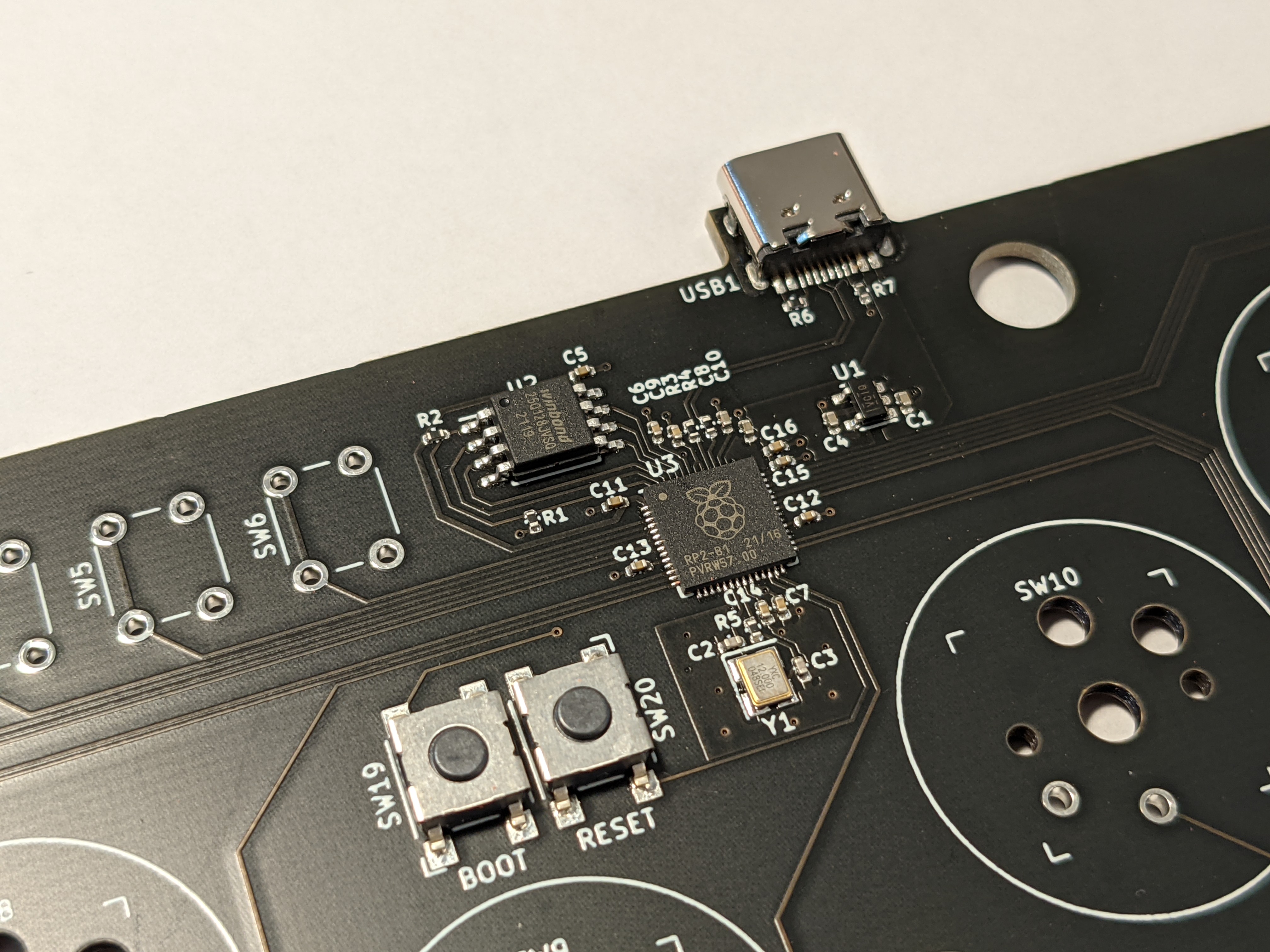
I was encouraged by this initial success, but I thought having to solder an Arduino board onto my PCB wasn't very elegant. Surely an Arduino is just another PCB and I should be able to include the microcontroller and all the other necessary components on my PCB and eliminate the need for an additional board. That's what I did for revision 2. I designed the board to use SMD (surface mount) components for everything except the keyboard switches and option buttons. I would probably not be able to solder them manually, but fortunately JLCPCB will happily do the assembly for you, you just have to provide two more files in addition to the Gerbers (list of components and their placement on the board). This time I was even more afraid that it wouldn't work at all, because there was a lot more I could mess up, but surprisingly the whole thing worked on the first attempt. Because it uses the same chip as the Pro Micro (ATmega32U4), I was able to use the same firmware. I was very happy, because even though manufacturing the boards was a little more expensive, it was suddenly starting to look somewhat like a real product.

Speaking of firmware, while it's easy to make a USB HID device that works with a PC or a PS3, it is unfortunately not the case with more modern consoles. From the PS4 onwards, Sony started restricting their systems to only work with licensed controllers. Each licensed pad or stick has some special chip with a private key inside it that lets it authenticate to the console. And DIY-ers are out of luck. Except you can buy PCBs that somehow get around Sony's restrictions (I don't know how they do it). I wanted a version of the Flatbox that was compatible with the PS4 so for revision 3 I went back to the idea of soldering an add-on board onto the main PCB. I chose the Brook PS3/PS4 board because of its small size. The only SMD components on the main board are the USB port and the two resistors that it requires.

The fourth and final revision of the Flatbox again has all the components on the main PCB and doesn't require an add-on board. It is similar to revision 2, but instead of the ATmega32U4 chip it uses Raspberry Pi's RP2040. It is the revision I like best, even though it's not compatible with the PS4 or the PS5.

All the files needed to make your own Flatbox are on GitHub, including KiCAD projects for the PCBs, 3D-printable models for the case and source code for the firmware.