2026-02-21

ByoWave Proteus controller

On paper, the ByoWave Proteus controller sounds like a perfect setup for a failed Kickstarter. A small team makes an attempt at a very ambitious first product, fails to deliver at all or delivers some severely cut down version of it after years of delay. Except in this case there was no Kickstarter and they didn't fail. This post is a random collection of thoughts and facts about the controller, presented in the hope that it might be useful to someone trying to decide if it's the right solution for them. All my experiences are with the as-of-now-current V2 edition of the controller.

You probably already know what it is if you're reading this, but let's start with a quick recap of the premise. The ByoWave Proteus controller is a modular game controller with a strong focus on accessibility. The idea is that you can build different controller shapes with it to match your individual needs. It consists of a number of rounded cubes that can be connected together, either directly or using additional spacer elements. There are two types of cubes: the power cube, which has a battery and is responsible for the wireless connection to your computer or console, and the analog stick cube, which looks the same except one face has an analog stick on it. Buttons and triggers are attached to the faces of the cubes. There's a four button attachment (ABXY and Xbox system buttons), a one button attachment, a d-pad attachment, a bumper/trigger attachment and a small analog stick attachment. It also comes with grip attachments that can be used for building traditional controller shapes.

The Proteus controller uses the Xbox One controller protocol (it is an officially licensed Xbox product) so out of the box it's compatible with Xbox One and Series consoles and Windows PCs. It also works on Linux if you have a recent enough (6.16+) kernel and it does work on the Steam Deck. It comes with a wireless dongle and the dongle is the only way it connects to the host. It does not have Bluetooth and it does not work wired (though it requires a wired USB connection to the PC for configuration, more on that below). You can use adapters to make it work with other consoles like the PS5, Switch or Switch 2.

The packaging it comes in is very nice and I'm definitely keeping it for storing modules that are currently not on my controler. The controller itself also just looks cool, which is perhaps not as important as whether it works well, but I think it's good that some effort went into it. Accessibility oriented controllers shouldn't have to look like hospital equipment. I like the snap-on covers with various playful designs.

It comes with two power cubes, which lets you use the kit to build two separate controllers (perhaps for a split configuration), but the wireless dongle can only talk to one controller at a time and the kit only comes with one wireless dongle, so to actually use it like that you'd have to buy an additional wireless dongle. Once you do you can use the "Assist" function on Xbox and Windows to make the two controllers work as one. I assume there's some technical reason why a single dongle can't talk to two power cubes simultaneously, but if would be really awesome if it could: split configurations make a lot of sense for a lot of people.

In addition to working as an Xbox controller ("GIP mode"), the controller can also emulate a mouse/keyboard combo ("HID mode"), which works on any platform that supports mice and keyboards. In this mode you can also define macros (strings of inputs) executed with a single button press.

The cubes and attachments come with default functions and you can build various configurations without ever having to use the configuration utility, just by disconnecting and reconnecting the modules to achieve different controller shapes. Which, by the way, you can do on the fly, without having to power down or disconnect the controller. But of course at some point you might want to change the default functions. This is done through a web application that connects to the controller over USB via the charging module. The charging module is just an attachment with a USB port and, as the name suggests, it's also used to charge the batteries inside the power cubes. Please note this USB connection is separate from the wireless dongle (which also plugs into a USB port of course). This means that when you're configuring your controller you might have both the dongle and another USB cable plugged into your PC. But this also means that you can plug the dongle into a different machine. So for example you can plug the dongle into your Xbox console while also having the controller connected to your PC using a USB cable. That way you can reconfigure it live and see the effects immediately in game.

The web based configuration utility uses WebHID to connect to the controller so it only works in the desktop version of Chrome (and possibly other Chrome-based browsers like Edge). Windows, Linux and Mac versions of Chrome are all fine. I love that this has now become the standard for configuring devices like this. Boo Firefox and Safari for not supporting WebHID.

Inside the configuration utility you can remap the buttons, sticks and triggers and switch between controller and keyboard/mouse modes. It shows a 3D view of your current controller shape and it updates live, which I think is a really nice touch. You can do most things you would expect, like change the "up" direction on the sticks, which is necessary given all the different ways you can put the modules together. Though there are still things that it lacks, for example even though it has a "shift" functionality, letting you assign a separate function to buttons when a certain button is held, this cannot be done in a "toggle" manner, enabling the shifted functions permanently without having to hold that button. ByoWave keeps adding new features so if there's some specific thing that you need for your setup, it's best to check as reviews written near the launch might not have all the current information.

The hardware itself seems robust, the modules connect securely and don't look like like they'll fall apart. But I haven't used it enough to speak about long-term durability.

I noticed that it takes 15+ seconds for the controller to connect to the wireless dongle once you turn it on. It's not a huge issue, but I'm used to other devices that connect immediately.

As I mentioned, the entire point of the controller is that you can build it in various shapes to suit your needs. An important aspect of that is that you don't have to use all the modules at all times. If the game you're playing only requires one analog stick and one or two buttons, you can build a configuration that only has those, that you can better use with one hand for example (in other words, it scales down nicely). That said, any given configuration you come up with will probably not be as good as a non-modular controller that was designed to have this shape from the start. If all you want to build is a PlayStation-controller-shaped controller then you're probably better of getting a PlayStation controller. Of couse, the whole point is that most shapes you can build with the Proteus are not available to buy off the shelf.

In addition to the modules the controller comes with, ByoWave designed and published files for 3D printable attachments for the controller. Using these files someone could conceivably design new shells or ways to connect the existing modules, making even more controller shapes possible. The caps on the analog sticks are also replaceable and there are some 3D printable designs for alternative caps fulfilling individual needs.

For example, I printed an attachment with an M6 thread insert and used the Proteus module as the balltop on an arcade stick lever.

Currently the Proteus controller is sold in two kits: one offers all the modules necessary to make a standard controller and the other only has a subset of the modules and comes with a one handed shell for a tabletop controller. It would be really good if the modules were available individually and I hope in the future ByoWave will let us pick and choose. Perhaps some more niche modules could be offered this way. There are signs that they're working on a motion (gyro) input module, which would be interesting (though likely hindered by the Xbox platform's lack of native support for it). I could also imagine button modules with various shapes and various actuation forces. Perhaps we could even have a module with one or more 3.5mm jacks that could be used to extend the setup with external buttons or switches, Xbox Adaptive Controller-style.

Speaking of the Xbox Adaptive Controller, the Proteus controller does not appear to work when the wireless dongle is plugged into the USB ports on the Xbox Adaptive Controller. This is somewhat weird because the XAC already knows how to talk to the Xbox Adaptive Joystick for example, which uses the same Xbox One controller protocol as the Proteus. So it would probably just be a matter of allowlisting some additional product IDs. This is not a huge issue because, as I mentioned, you can use the "Assist" function on Xbox and Windows to make two controllers work as one, so you can use it to combine the XAC and the Proteus controller into one. But if you're using the XAC as part of your Switch or PlayStation setup using adapters, or you're on Steam Deck, you don't have this option.

But on a related note, I'm happy to report that the Proteus controller works great with HID Remapper in both GIP (controller) and HID (keyboard/mouse) modes. You could make it compatible with the Nintendo Switch and Switch 2 this way or enhance its functionality beyond what the Proteus can do by itself. Indeed you could also use HID Remapper to make the Proteus controller compatible with the Xbox Adaptive Controller or use it to make two Proteus controllers work as one on non-Microsoft platforms.

On the Proteus controller, the controller and keyboard/mouse modes are mutually exclusive, the controller is either in GIP mode or HID mode. First party Xbox controllers like the Xbox Adaptive Controller and the Elite controllers can be configured to send keyboard inputs while working as a controller. I wonder if this is something that ByoWave could add to the Proteus controller in the future.

I haven't done any proper performance testing with the Proteus controller. In some informal tests I have never seen it send more than 50 reports per second. This probably has consequences for input latency. Ultimately you will have to decide whether this matters to you. I doubt it makes any difference in casual play. It might make a difference for pro players, but I don't think they're the target audience here anyway.

The biggest downside for me is the lack of native PS5 compatibility. I don't know the reasons for it and I don't know what it would take to make it possible. My guess is we would need a separate wireless dongle for the PS5, which I think a lot of people would be okay with if it meant not having to deal with adapters. But there might be some bigger non-technical obstacles.

I can't tell you if the ByoWave Proteus controller will be the right fit for you, but I hope I have provided some data that will help you make an informed decision. Thanks for reading.

2026-01-02

2025 roundup

Here's some stuff I did last year.

  • Pixelrings: LED earrings programmable in Python.
  • RP2040-RS232: RS-232 adapter with an RP2040 chip. Can be used to adapt ancient serial mice or 3D mice for modern systems or as a generic serial-to-USB adapter.
  • Some new Flatbox revisions:
    • rev4.1: an updated RP2040 variant with a USB host port
    • rev4.1wasd: same but with a WASD layout
    • rev8: an RP2350 variant with a USB host port
    • rev9: a SAMD21 variant
    • rev10: an STM32G0B1 variant
  • Portable Gamepad Firmware: a wired game controller firmware. Through the power of Zephyr the same code runs on many different platforms with the hardware details defined in devicetree overlays. Functionality is super basic right now, but we have builds for many different boards, including the Flatbox variants above. Does 8000 Hz on hardware that supports it (currently Teensy 4.0).
  • HID Remapper now has a proper website and a forum. Also builds for the RP2040/RP2350 Flatbox variants.

2025-03-07

What I've been up to

I used to post on this blog whenever I finished a project, but these days I typically just put it on GitHub and call it a day. I think some of these projects deserve separate posts, but just in case I never get around to it, here's what I've been doing for the last three years or so.

  • HID Remapper: programmable adapter for USB input devices. Remap buttons, make keyboards work as game controllers, make joysticks work as mice or vice versa. Lots of cool stuff, including accessibility applications.
  • Flatbox: this one got its own post, but I've made a few more variants since then, including a wireless one!
  • Trackballs: I made a PCB with an RP2040 chip and a PMW3360 mouse sensor that can be used to quickly prototype mice and trackballs. Then I made a few trackballs using it. Notable mentions: spherical trackball, two-ball trackball, trackball with twist-to-scroll, trackball with scroll ring.
  • Slimbox Generator: a website for rapid prototyping of leverless controller layouts. Generates 3D-printable files.
  • PlayStation Access Controller Profile Editor: a website for editing the button mapping on a PlayStation Access controller without a PS5.
  • HID Forwarder: a system for sending synthetic inputs from a PC to something like a Nintendo Switch, over serial, wifi or Bluetooth, with potential accessibility applications.
  • Slimbox BT: wireless game controller firmware for nRF52 chips.
  • Zero Latency Gamepad: lots of products claim low latency, mine actually comes very close to what's physically possible on Full Speed USB.
  • Latency tester: speaking of latency, I made my own latency tester for game controllers and other USB input devices because I wasn't happy with existing ones.
  • Spaceball 2003 USB adapter and Magellan/SpaceMouse USB adapter: these let you use ancient RS-232 3D mice with modern software.
  • Google Meet mute button: a physical button that lets you mute your microphone on a Google Meet call regardless of which window is active and has a nice LED indicator to show when you're on call and if the microphone is muted.
  • PS5 adapter for old Logitech wheels: play Gran Turismo 7 with the Logitech Driving Force Pro wheel from 2003. Possibly other old Logitech wheels.
  • RPM lights for Gran Turismo 7: use GT7 network telemetry to make pretty physical shift lights for your virtual car.
  • Screen Hopper: smart KVM switch that lets you just drag the cursor from one computer to another, no software required. A hack on top of HID Remapper.

2022-07-27

DIY Surface Dial

Microsoft's Surface line of hardware has some nice computers and accessories. Among the accessories there's the Surface Dial - a Bluetooth knob that can do things like volume control, scrolling, undo/redo and some other functions in certain applications, mostly artist-oriented. For some reason the physical form of the Surface Dial appeals to me, but since its price is not exactly in the impulse buy territory and I don't have a practical need for it, I never got one. But now I have made my own version of it. It's not as nice as the real one and it's missing some of the functionality, but it really does work as a Surface Dial in the software that supports it.

There are two aspects to this device, making the physical hardware and programming it so that Windows recognizes it as a Surface Dial.

From the hardware perspective, we need two things - a way of detecting the dial's rotation and a button. On the real Surface Dial the entire knob works as a button, but in my version, there's a separate button in the middle, made using a mechanical keyboard switch. As for the dial itself, instead of using an off-the-shelf rotary encoder, I made my own using small neodymium magnets and two Hall effect sensors. Its principle of operation is the same as with other incremental encoders, the sensors are oriented so that their signals have a phase difference. In theory we could get better resolution by using the full resolution of the sensors' output, instead of treating them as binary, but I haven't done that. The resolution I got is determined by the number of magnets (48).

I designed the case for the device in Fusion 360 and 3D printed it. The dial sits on a 6806 ZZ bearing and has a very satisfying feel. Here's what it looked like during assembly.

For the microcontroller I chose the Adafruit QT Py RP2040, it's small and uses the RP2040 chip from Raspberry Pi (it has a similar form factor to Seeed Studio's XIAO RP2040).

Since we're talking about Microsoft, I half-expected the Surface Dial's protocol to be some proprietary nonsense that would require reverse engineering to replicate. Imagine my surprise when I found out that it's actually standard HID and there's proper documentation for it. All you have to do is put the right stuff in the HID report descriptor and it works similarly to a regular USB mouse or keyboard.

I put all the code and 3D-printable files on GitHub, along with a list of components used and instructions how to put them together.

2022-07-09

Two mice, two cursors

I always thought that when you connect two mice to a computer, there should be two mouse cursors, one for each mouse. Unfortunately that's not really how it works on modern operating systems, at least not by default. Software add-ons exist that draw a second cursor for the second mouse (and also perform some tricks to make button clicks work as expected). I'm sure they work fine, but I came up with a pure hardware solution to the problem that requires no special software running on the host. Here's a video demonstrating this solution.

What you can see here is two mice, connected through a USB hub to an Arduino Leonardo with a USB Host Shield. The mice are wireless, but they use 2.4 GHz USB receivers so they're effectively USB devices. The Arduino is connected to the computer and acts as a USB mouse.

The Arduino reads inputs from the two mice, does its magic, and sends the resulting inputs to the computer. What's the trick that makes the computer display two cursors? If you look closely, you'll notice that the two cursors flicker a bit. That's because they're not really two cursors, instead it's just the one normal cursor oscillating quickly between two positions on the screen, appearing as two due to persistence of vision. The Arduino keeps track of the X/Y positions of both cursors and updates them based on the inputs received from each mouse. Then it alternates between the two causing the illusion of two cursors. To be able to do that it uses absolute cursor positioning, unlike a regular mouse, which only sends the X/Y deltas and doesn't know where on the screen the cursor is at any moment. (I have previously used absolute cursor positioning for both good and evil.)

One remaining problem is what to do when you click a button on one of the mice. The user will naturally expect for the click to happen at the screen position of the cursor corresponding to that mouse. So we can't keep alternating between the two cursors. For as long as the button is pressed, we only send the cursor position of the mouse that's doing the clicking. This means that the second cursor disappears for a brief moment, but the clicks work as expected.

If you want to play around with it, I posted the source code on GitHub. It uses the standard USB HID protocol and works with Windows, Linux and Mac, without any additional software needed on the computer.

2022-07-07

Razer Raion padhack

One of the problems when making a custom fightstick (arcade controller for fighting games) is modern console compatibility. While it was easy to make an Arduino or similar board work as a USB controller for the PS3, unfortunately it is no longer the case with the PS4 and PS5. Only licensed controllers work with them due to restrictions introduced by Sony. Every licensed controller has a private key embedded in it that allows it to perform some kind of authentication when connected to a console. One solution to this problem is a practice known as padhacking: taking the insides of an existing licensed controller and transplanting them into a different enclosure, for example a fightstick-shaped one, carefully soldering wires between buttons and the right places on the donor PCB.

In theory you can use any controller for this, like a DualShock 4 or a DualSense, but it makes sense to choose one that will be relatively cheap to obtain and also easy to solder to. One such controller is the Razer Raion. It was originally released for the PS4, but since it qualifies as a "specialty peripheral", it also works in PS5 games. I got one and made a mixbox-layout fightstick using its PCB.

First I had to figure out where the solder points that I need are on the PCB. Fortunately I found this helpful tweet and with this information it was a fairly straightforward job.

The rest of the fightstick was similar to what I've done previously, in fact I just modified one of the designs to accomodate the Raion PCB. Here's what it looks like inside. As you can see it uses common ground.

One thing to keep in mind when converting a controller like this is the matter of SOCD cleaning - what happens when you press opposing direction buttons at the same time? Most traditional controllers don't have to worry about this because it's physically impossible to simultanously trigger opposing directions on them. But when you make a stick that has separate buttons for up, down, left and right, that can be pressed independently, it's something you have to start thinking about. In case of the Razer Raion, it uses a scheme called first input priority, meaning that if you press and hold left, then press and hold right, it will keep sending left. When you release left, then it will start sending right. If I didn't like this, I'd have to add an external SOCD cleaner between the buttons and the Raion PCB.

I posted the 3D-printable models for this stick on Printables. It uses Kailh low profile (choc v1) mechanical keyboard switches for the buttons. Here's what the final result looks like.

2022-07-06

Flatbox

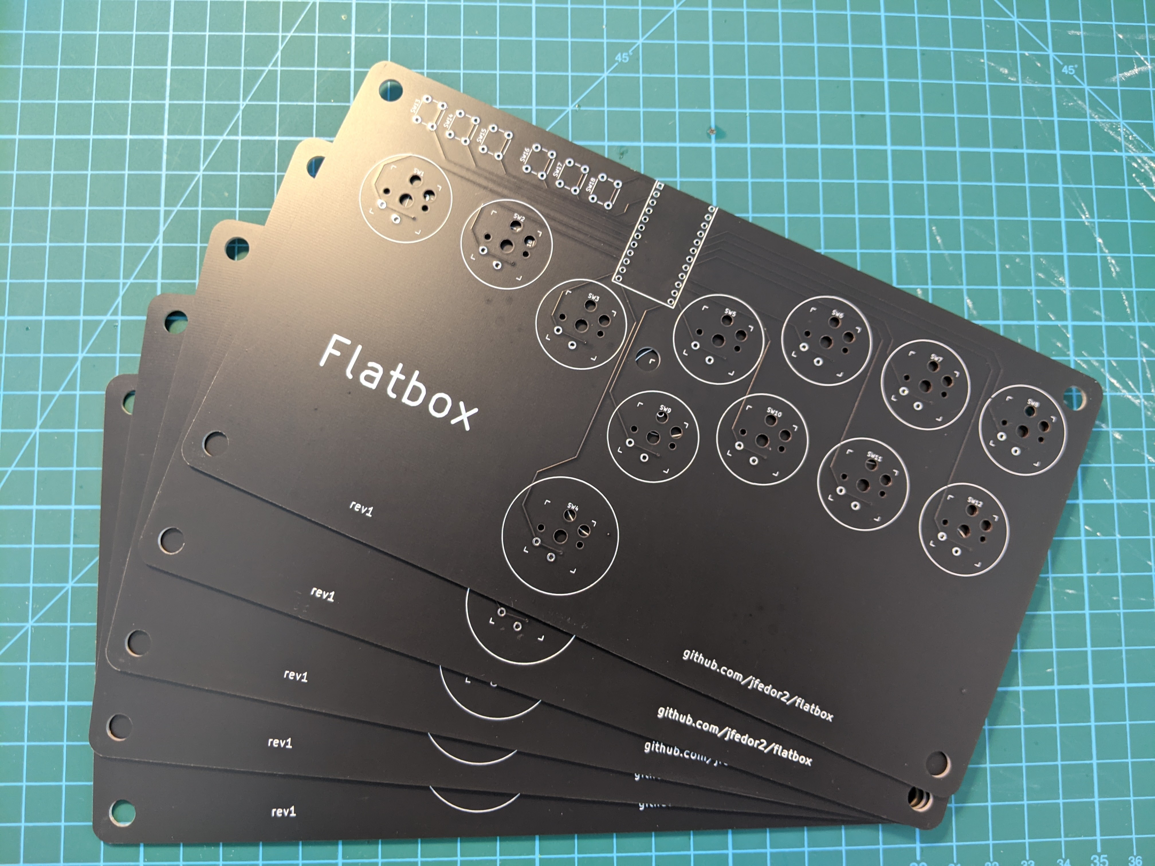
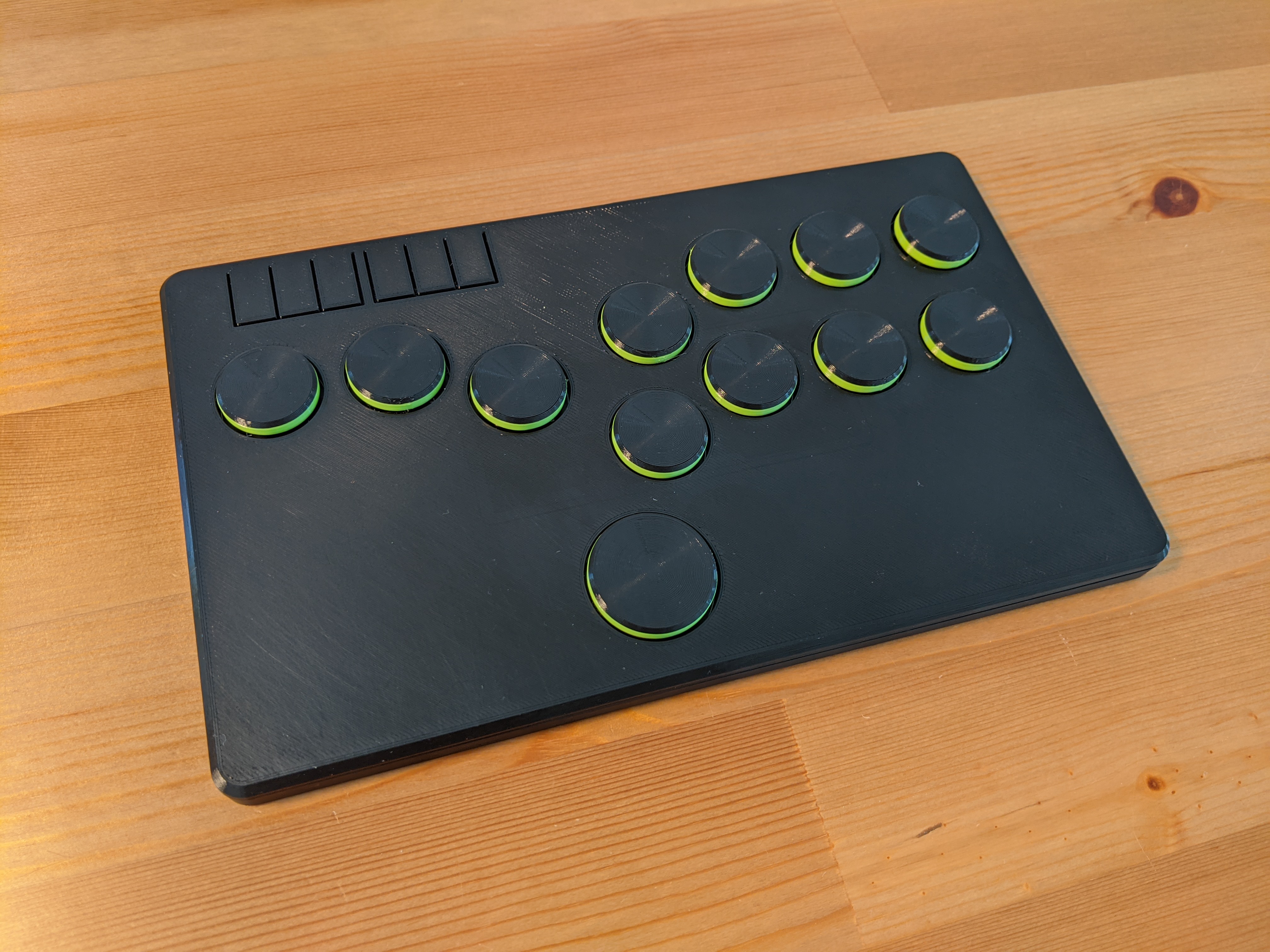
Having previously made some 3D printed fightsticks (arcade controllers for fighting games) that were just plastic boxes with holes for arcade buttons or mechanical keyboard switches, I started thinking, could I make one that's even thinner? On my previous designs I just soldered wires to the keyboard switches, but they're really intended to be soldered onto a printed circuit board. Using a PCB instead of the wire spaghetti inside the case seemed like a good way to shave a few millimeters off. And it turns out there are companies in China that will manufacture a custom PCB for you for very reasonable prices. And thus the Flatbox was born. I ended up making four revisions of it.

Up to this point I was using Arduino Pro Micros as the brains of my fightsticks, so it seemed natural to start with a PCB that I could solder a Pro Micro onto. The PCB would just serve as a connection between the Arduino's pins and the keyboard switches (I used Kailh choc v1 low profile switches). I designed my board in KiCAD, arranged the switch footprints in a hitbox-style layout, generated the Gerber files and sent them off to JLCPCB for manufacturing. After some days I was excited to receive a package with my boards inside.

I've never done anything like this before so I wasn't sure if the boards would even work at all. I'm used to prototyping on breadboards, if you make a wrong connection there it's usually not a big deal and it's a matter of seconds to correct it. Here if I made a mistake, not only would it cost money, but I'd also have to wait a week or two for another package from China. But fortunately everything worked great! I quickly designed and 3D printed an enclosure for it. I was very pleased with the result, just 10 millimeters thick!

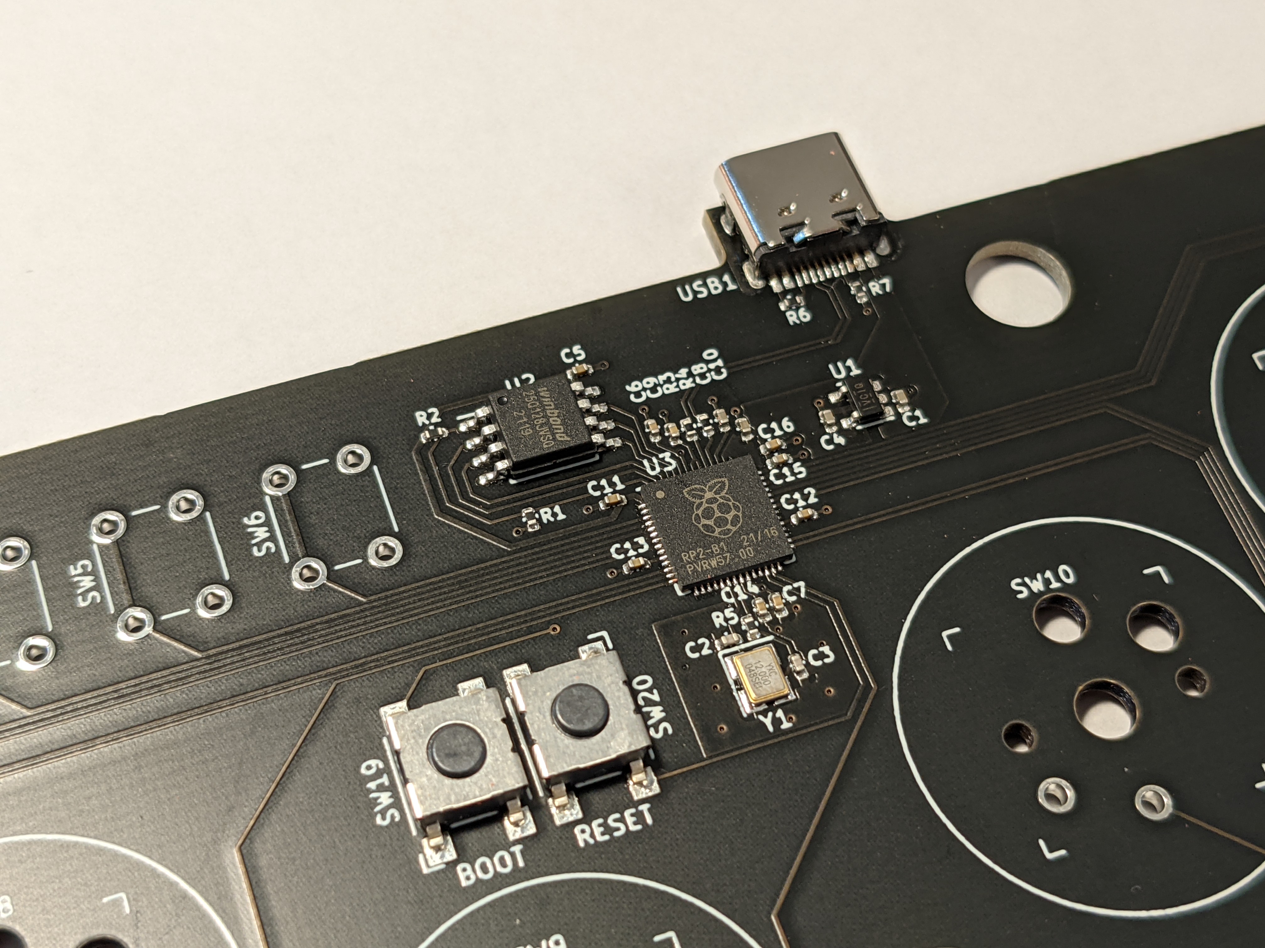
I was encouraged by this initial success, but I thought having to solder an Arduino board onto my PCB wasn't very elegant. Surely an Arduino is just another PCB and I should be able to include the microcontroller and all the other necessary components on my PCB and eliminate the need for an additional board. That's what I did for revision 2. I designed the board to use SMD (surface mount) components for everything except the keyboard switches and option buttons. I would probably not be able to solder them manually, but fortunately JLCPCB will happily do the assembly for you, you just have to provide two more files in addition to the Gerbers (list of components and their placement on the board). This time I was even more afraid that it wouldn't work at all, because there was a lot more I could mess up, but surprisingly the whole thing worked on the first attempt. Because it uses the same chip as the Pro Micro (ATmega32U4), I was able to use the same firmware. I was very happy, because even though manufacturing the boards was a little more expensive, it was suddenly starting to look somewhat like a real product.

Speaking of firmware, while it's easy to make a USB HID device that works with a PC or a PS3, it is unfortunately not the case with more modern consoles. From the PS4 onwards, Sony started restricting their systems to only work with licensed controllers. Each licensed pad or stick has some special chip with a private key inside it that lets it authenticate to the console. And DIY-ers are out of luck. Except you can buy PCBs that somehow get around Sony's restrictions (I don't know how they do it). I wanted a version of the Flatbox that was compatible with the PS4 so for revision 3 I went back to the idea of soldering an add-on board onto the main PCB. I chose the Brook PS3/PS4 board because of its small size. The only SMD components on the main board are the USB port and the two resistors that it requires.

The fourth and final revision of the Flatbox again has all the components on the main PCB and doesn't require an add-on board. It is similar to revision 2, but instead of the ATmega32U4 chip it uses Raspberry Pi's RP2040. It is the revision I like best, even though it's not compatible with the PS4 or the PS5.

All the files needed to make your own Flatbox are on GitHub, including KiCAD projects for the PCBs, 3D-printable models for the case and source code for the firmware.

2022-07-04

Fightsticks

Fighting games like Virtua Fighter, Tekken or Street Fighter originated at the arcades and have traditionally been played on cabinets with heavy duty joysticks and buttons. Even though they're mostly played on consoles and PCs these days, many players use arcade sticks modeled after the arcade cabinets, either because they consider them superior to controllers or simply because they enjoy their old school look and feel.

Arcade stick parts like buttons and joysticks can be bought separately so it's fairly easy to make your own stick. All that's needed is some kind of a box and a microcontroller that will read the state of the buttons and send the appropriate inputs to the PC or console. Not suprisingly, there's a thriving DIY community of fightstick makers.

I designed a few arcade stick cases meant to be 3D printed. The ones shown below all use an Arduino Pro Micro as the brains, running this firmware, compatible with PC and PlayStation 3. If you like any of them and want to try making your own, I've posted all the 3D-printable models on Printables, along with more pictures and details on how to make them.

The first one uses the most classic layout, with a Sanwa JLF joystick, 30 mm action buttons and 24 mm option buttons at the back. I made versions with 6 and 8 actions buttons.

The traditional appeal of arcade sticks doesn't mean that things are standing still. Some new stick layouts have emerged over the years, the most popular of them probably being the hitbox layout, which ditches the actual joystick and instead uses four buttons for the direction inputs. The large button at the bottom is the jump button and it's meant to be operated by either your left or right thumb. This layout seems best suited for 2D games like Street Fighter. You can see my take on this control scheme below.

Another layout that uses buttons instead of the joystick is the mixbox layout. It uses keyboard keys in a more familiar WASD shape for the direction inputs. In my opinion it's better for 3D fighters like Virtua Fighter and Tekken than the hitbox layout. Here's my version.

In addition to new stick layouts, people have also started putting alternative parts in their sticks. One move that's obvious in retrospect is to try using mechanical keyboard switches instead of the traditional arcade buttons. There are many different keyboard switches to choose from and they also allow the fightstick case to be much slimmer. Here's my attempt at a hitbox-layout controller that uses Kailh low profile keyboard switches and is just 14 mm thick (I call it the Slimbox).

Similarly, here's a mixbox-layout version of the same idea (Slimbox M).

2021-01-27

Bluetooth trackball Mark II

I made a Bluetooth trackball in which all the electronics are inside the ball. The ball is the entire trackball. Here it is in action:

Inside the ball there's a microcontroller and a set of sensors that together with some clever algorithms allow the microcontroller to know the ball's absolute orientation in 3D. When the ball is rotated, it sends the appropriate commands to the computer over Bluetooth to move the mouse cursor. Oh, and the keyboard in the video is a completely separate USB device, it's only used for mouse clicks and doesn't interact with the ball in any way.

This is actually the second iteration of the project. While I was very proud of my previous attempt, it had some undeniable shortcomings and was generally a proof-of-concept quality device. This new version improves upon it in many regards, to the point where I think it could possibly be used on a day to day basis as a replacement for your regular mouse. Specific features include:

  • an nRF52840 chip along with LSM6DS33 accelerometer/gyroscope and LIS3MDL magnetometer
  • a wirelessly rechargeable 500 mAh battery
  • battery level reporting over Bluetooth
  • more robust "up" calibration
  • fully sealed construction allowing for smooth rolling of the ball

I used Adafruit's Feather nRF52840 Sense, it has all the necessary sensors onboard. The other components are a lipo battery, a wireless charging coil and two reed switches, one of which is connected to the board's "En" pin, allowing us to turn the device off with an external magnet, the other is connected to a GPIO pin and is used to trigger the "up" calibration.

The ball is 65 mm in diameter and is made of two 3D printed halves. After putting the electronics inside I glued the two halves together and smoothed the surface by progressing through increasingly finer grits of sandpaper. It rolls pretty smoothly on 2.5 mm zirconium oxide bearing balls, though it's still admittedly not as smooth as a real trackball. I made a few bases in various shapes for the ball to roll on, they are just pieces of 3D printed plastic and don't have any electronics in them.

To charge the battery inside the ball I also made a special base that has a wireless charging coil inside and is powered with USB (or any 5V source). It also has a strategically placed magnet that can be used to trigger one of the two reed switches inside the ball, one will turn the device off, the other allows for setting the logical "up" directon of the trackball (by itself the trackball doesn't know which direction should move the mouse cursor up, so you can set it by putting a magnet near one of the reed switches and rotating the ball around the vertical axis).

The Arduino code and 3D models are on GitHub.

2020-11-06

Dactyl Manuform build log

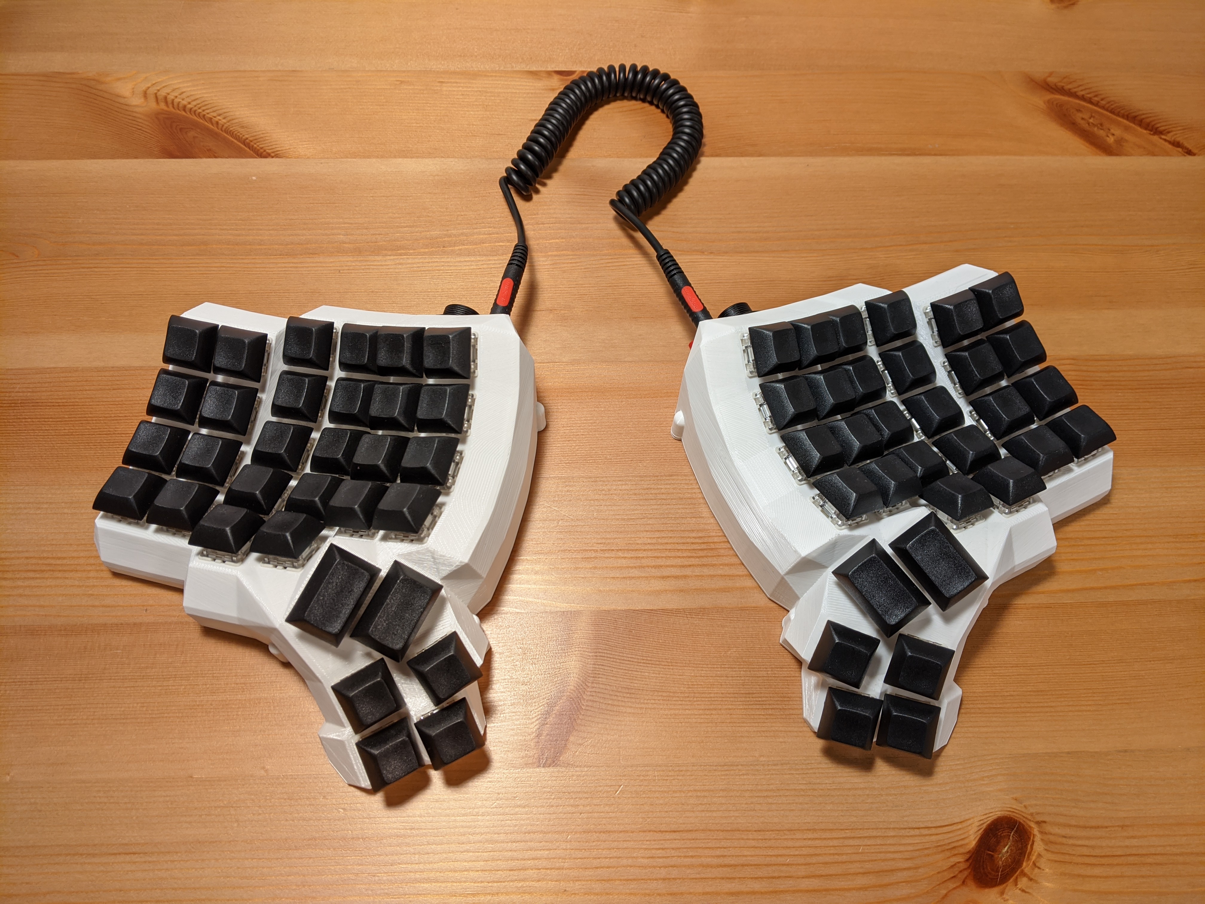
I made an ergonomic split keyboard using the Dactyl Manuform design, specifically the 5x6 version. I'm going to describe the process in the hope that it will be useful to someone considering making one. Here's what the final product looks like:

The Dactyl Manuform, made by Tom Short, is a modification of the original Dactyl keyboard design by Matthew Adereth. Matthew has given an entertaining talk on his design process. It won't really help with building the keyboard, but it has some nice bits on keyboard history in general.

The keyboard is controlled by an Arduino Pro Micro (one in each half) which is running the QMK firmware. This firmware is used by many keyboards, both hand-made and mass-produced and it has several useful features and allows you to customize the keyboard to a much greater extent compared to what's possible on a normal one.

Let's get to it. First we need to decide on the general shape of the keyboard and 3D print the case (or have someone 3D print it for us). I went with 5x6, meaning 5 rows and 6 columns of keys, which translates to having a row for the 0-9 keys, but not for the function keys. The fifth row only has two keys and there's also a 6-key thumb cluster. The 3D models are generated by a Clojure program that outputs a .scad file that is then converted to STL using OpenSCAD. Things like the number of rows and columns and the angles are all configurable in the Clojure code. If you don't want to mess with Clojure, there's an online generator that lets you customize some things and gives you a .scad file.

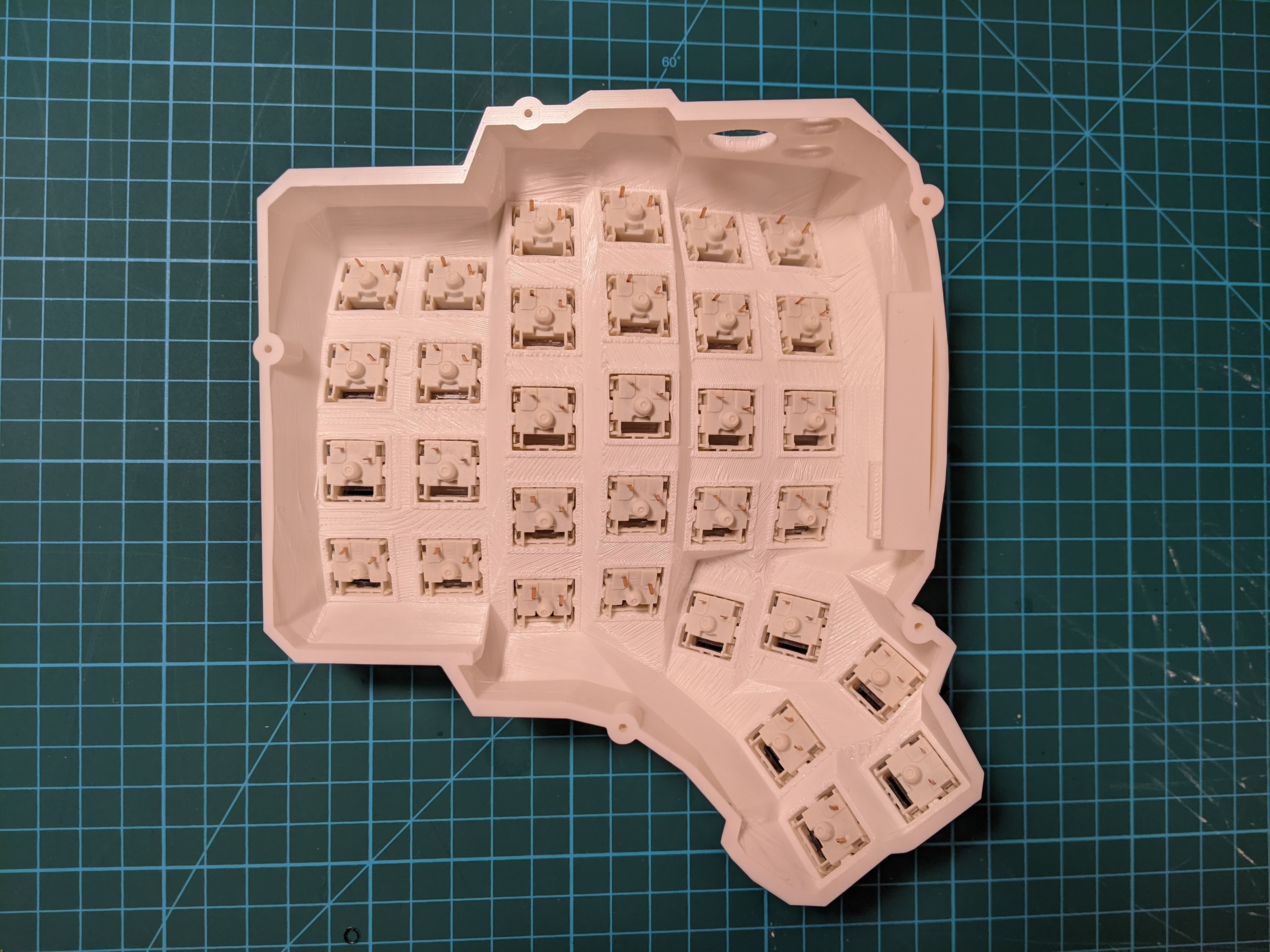
Here's what it looked like after printing in my case:

I've made some modifications to the design, fixing some issues and changing the holes for the ports to circular ones (so that they can easily be used with panel-mount sockets). I also added a hole for a reset button, which is useful when programming the thing. You can get my STL files on Thingiverse. People often cut the bottom plate from acrylic or even metal, but I just 3D printed it like the rest of the case. I also didn't use heat set inserts and just went with wood screws. Oh, and I really recommend using Cura with tree supports when printing the case. Normally I use PrusaSlicer for everything, but in this case the supports it generated were practically impossible to remove. Printing each half took about 20 hours on my Prusa MK3S.

In addition to the case, here are the parts that I used:

  • Arduino Pro Micro (2x)
  • Gateron Brown switches (64x)
  • DSA profile keycaps (60x 1u and 4x 1.5u)
  • 1N4148 diodes (64x)
  • panel-mount micro USB socket (2x)
  • panel-mount 3.5mm TRS socket (2x)
  • panel-mount momentary switch (2x)
  • some hookup wire, 24 AWG
  • 3x10mm wood screws for attaching the bottom plate (10x)

Then we need to actually wire the thing. To avoid having to use a separate wire going to the controller from every key, a matrix circuit is used, meaning the keys are arranged into rows and columns and there's a diode connected to every key. There's a wiring diagram on Tom Short's repository, but it's somewhat confusingly described as "alternative". The alternative one is the one you want.

First, we put the switches into the case. They are only press-fit mounted so be careful when removing keycaps as you can easily pull the switch out along with the keycap. Here's what it looked like before any soldering:

For the rows I used a method where no additional wire is required and the diode leads are used to connect one key to the next. Pay attention to the orientation of the diodes!

Then I wired the columns (please excuse my poor soldering skills):

Then the rows and columns need to be wired to the right pins on the Arduino:

The 3.5mm socket and the reset button also need to be wired to the Arduino and the whole thing needs to be repeated for the other side:

Then we mount the USB socket, connect it to the Arduino and try to squeeze everything inside the case. In theory the case includes a holder for the Arduino board, but I ended up not using it. With all the wires the board doesn't move around too much. I put some foam between the switches and the Arduino to avoid shorts.

Before attaching the bottom plates, test the thing! Suprisingly in my case it worked the first time with no issues.

A quick note on how the two halves work together. Each half of the keyboard has an Arduino Pro Micro board that's wired to the key matrix. In theory you could just connect each half separately to the computer via USB and it would work. But then we'd end up using two USB ports just for the keyboard and we wouldn't be able to do some clever tricks with the layout that require communication between the two halves. So instead the way it works is only one half is connected to the computer through USB and the two halves are connected to each other using a serial interface - that's what the 3.5mm jacks are for (BTW, don't connect or disconnect the 3.5mm cable while the keyboard is connected over USB):

How does the Arduino know if it's the left or the right half? By default the USB cable is supposed to be connected to the left half so that's how it decides: if USB is connected, then it knows it's the left half, otherwise it's the right half. I didn't like that very much, I wanted the freedom to connect USB to any of the halves. Fortunately that variant is fully supported, you just have to store the left/right identity in EEPROM when flashing the board. To achieve that I commented out the #define MASTER_LEFT in keyboards/handwired/dactyl_manuform/5x6/keymaps/default/config.h and uncommented #define EE_HANDS. Then to flash the left half I do:

make handwired/dactyl_manuform/5x6:default:avrdude-split-left

And to flash the right part I do:

make handwired/dactyl_manuform/5x6:default:avrdude-split-right

When the software tells you to reset the board, you double tap the reset button quickly. If you don't want to mess around with compiling the firmware yourself and generally want to avoid the command line, there's this thing called the QMK Toolbox that has a nice GUI.

And now for the fun part, defining your own layout! There's an online configurator where you can define your key mapping and download a JSON configuration file. Or you can modify the keymap.c file in keyboards/handwired/dactyl_manuform/5x6/keymaps/. If you go the JSON route, just delete the keymap.c file and put a keymap.json file in the same directory. Then flash the firmware using the commands above. Or if you're using the QMK Toolbox, the online generator can compile the thing for you.

I hope this quick report helps someone, have fun if you decide to build one yourself. I really think it's a nice project!

2020-10-18

Lean back to scroll

You know those days when lifting a finger to scroll a website seems like to much of an effort? No, of course not, me neither. But just in case I made this so I can scroll just by leaning back in my chair:

If you look closely there's Adafruit's Feather nRF52840 Sense board attached to the back of the chair. It uses the onboard sensors to figure out the angle of the chair's back and if it's over a threshold it sends scroll down events to the computer (using the standard Bluetooth mouse protocol so it works with any OS). To set the "zero" position you press the "user switch" button on the board.

Here's the Arduino code.

2020-09-27

Hat mouse

I've been playing around with orientation sensors and Bluetooth HID recently. Today I'd like to show you what is perhaps my most practical application of those yet. I made a head mouse, also known as an air mouse, or in my case, a hat mouse:

The device is attached to a hat and you move your head around to move the mouse cursor on the screen. It uses the standard Bluetooth mouse protocol so it works with Windows, Mac and Linux with no additional software running on the computer. The board used is Adafruit's Feather nRF52840 Sense. The way it works is it reads accelerometer, gyroscope and magnetometer data, puts it through a sensor fusion algorithm to get orientation and then uses the yaw and pitch values to position the mouse cursor on the screen. It uses absolute cursor positioning so any given head orientation corresponds to a fixed cursor position on the screen. To reset the center position, you press the "user switch" button on the board.

Here's the Arduino code. In addition to the Feather board we need some way to power it. I used this lipo battery, but the board can also be powered over the USB port so a small power bank could work as well.

As with some of my previous custom devices that work as a mouse, unfortuntely the hat mouse has no way of performing button clicks yet. In the video above I'm using a separate USB foot switch for clicking. Depending on the movement limitations of the user, something like a sip-and-puff switch might be more appropriate (same goes for the orientation reset button that's currently located on the board). The Feather nRF52840 Sense board has a lot of sensors in addition to those that we're currently using for the orientation. Perhaps the pressure sensor or the light sensor or even the microphone could be used to make entirely head-operated switches. I have some ideas, but I decided to treat that as a separate project.

2020-09-21

Plotting sensor data with MS Paint and Bluetooth HID

I have recently discovered that the HID mouse protocol supports absolute cursor positioning in addition to the more common relative mode. I think that opens interesting possibilities, one of them being we can plot real-time charts in MS Paint with no additional software running on the computer, using just the standard Bluetooth mouse protocol:

The board used above is Adafruit's Feather nRF52840 Sense, which has Bluetooth LE and lots of sensors. On the video we're plotting readings from the accelerometer. The chart is drawn by simulating mouse and keyboard inputs (keyboard is used to clear the screen when we reach the right edge).

Here's the Arduino code.

2020-09-20

USB "rubber ducky" with mouse input

Perhaps you're familiar with a type of device commonly referred to as a USB rubber ducky. It's a seemingly innocent device that looks like a regular USB drive, but when connected to a computer, it acts as a USB keyboard and sends malicious keystrokes to the victim's machine, as if a human typed them (but faster). The commands sent can download some unwanted software or open a reverse shell and do nasty stuff in general.

So I thought why stop at keyboard, why not also pretend to be a mouse, launch Paint and draw something funny:

The main challenge here is that a regular mouse doesn't really know where the cursor is on the screen. It only sends relative position changes like "move the cursor 7 units to the right and 2 units down". Depending on the sensitivity setting on the user's system, it might correspond to a different distance in pixels. When you add mouse acceleration into the mix, it's not really practical to try and guess where the cursor will end up being.

But, as is turns out, the mouse HID protocol also allows for absolute cursor positioning and all the major desktop operating systems support this mode (perhaps because touchscreens and graphics tablets use it?). With that knowledge, the task becomes easy, as we can just say "move the cursor to position X, Y".

I used a Digispark with a modified version of Adafruit's TrinketHidCombo library for the demo above. Here's the Arduino code.

2020-09-08

Human trackball

Remember Logitech's April Fools' video from 2017? The one where the gym ball works as a trackball? I made that for real:

I did this as kind of a detour while working on the next version of my Bluetooth trackball from last year (stay tuned for that). I found a board on AliExpress that has the nRF52832 Bluetooth chip from Nordic, an MPU-9250 9DOF sensor, a built-in battery charging circuit and comes with a lipo battery attached. Originally a development board for a fitness bracelet, it looked like a pretty good match for my needs.

For this application I just attached the board to the gym ball using scotch tape (and tried to avoid sitting on it or crushing it by rolling the ball).

The software is derived from my previous IMU-based Bluetooth trackball attempt. This time I decided to do the sensor fusion algorithm in software - even though the MPU-9250 is better than the MPU-6050 because it has a magnetometer (3 more DOFs!), its onboard algorithm was not updated to make use of it - it still only uses the accelerometer and gyroscope. So I used Adafruit's library implementing Sebastian Madgwick's sensor fusion algorithm. I also used Sandeep Mistry's Arduino core for the nRF52832 chip and his BLEPeripheral library for Bluetooth. I programmed the board using Nordic's nRF52 DK development kit.

You can find the code here. Also included is a sketch for calibrating the magnetometer that sends the data over Bluetooth serial (I used Adafruit's Bluefruit Connect app to read the data). And since the gym ball itself has no way of performing button clicks, I used a foot switch connected to a Digispark for clicking the mouse. A sketch for that is also included.

Even though it looks like a trackball, the ball works more like a joystick in this case: when you tilt it to the right, the cursor moves as long as the ball is kept in that position and stops moving when it is returned to the neutral starting position. Right now it's not really a practical mouse or trackball replacement, but I believe that with some fine tuning it might become a viable option. Another possibility would be to only use it for scrolling, not moving the cursor, which I haven't tested, but it should be an easy modification.

Can't wait for Logitech's next year April Fools' video!

2020-03-09

Bathroom occupancy monitor

Don't you hate it when you get up from your desk at work to go to the bathroom, only to find out that all the stalls are occupied? I did, so I made a website that shows the current status of each stall. It normally looks something like this:

To make this possible, I installed a 433 MHz door/window sensor on each stall door. Somewhere nearby I put an ESP8266 module with a 433 MHz receiver board. Each time a stall door is locked or unlocked, the module gets a signal from the sensor and passes it on to a Firebase cloud function that saves the current state and timestamp in a database. Finally there's a website that reads the database and displays the current status for everyone to see.

Even though the sensors I used are normally meant to detect when a door (or window) is opened, what I really wanted to detect in this case is whether the doors are locked. I achieved that using a zip tie and a neodymium magnet attached to the door lock:

What's nice about these sensors is that they're cheap, require no modification, and will run on a single AAA battery for many months. One thing to keep in mind is that it's important that the sensors send a signal every time they detect a state change in any direction, not just when they detect that the door/window has just been opened. Not all of the sensors on the market do that and sometimes it's not clear from the description.

The ESP8266 board I used was a Wemos D1 mini clone, here's what it looks like with the 433 MHz receiver board:

The rest is software, the ESP8266 is running an Arduino sketch and the web part uses Firebase. You can see the whole thing here. The cloud function part isn't strictly necessary, the ESP8266 could write to the Firebase database directly, but it was much easier for me to do it this way.

Right now I'm only using the website to know if the bathroom is occupied, but it might be interesting to gather some statistics, such as the average time people spend in the bathroom or how likely it is to be occupied depending on time of day.

2020-02-15

Darkroom enlarger timer

I have recently started making traditional prints of my analog photos and it is a lot of fun in itself, but naturally I am also treating it as an excuse to play with some electronics. I have previously described a simple timer I made for measuring how much time each print spends in the developer and fixer trays. Today I'd like to present my solution for the more important type of darkroom timer: the one that controls the exposure time on the enlarger. Here's what my setup looks like:

The enlarger lamp is connected through a reprogrammed Sonoff S20 wifi smart plug. It runs a simple HTTP server written in MicroPython. It responds to three commands: "on", "off" and "expose". The last one takes a duration in milliseconds and switches the lamp on for that time.

The second component is a smartphone app written in Flutter, so it should in theory run on both Android an iOS, but I have only tested on Android. It lets the user specify the exposure time, either directly or using a simple test strip mode. In test strip mode, exposures are made in such a way that if you cover a larger part of the paper before each exposure, the resulting exposure times of each part will be increasing in configured fractions of a stop.

Finally there's a footswitch, which is just a pedal converted into a USB keyboard using a Digispark (which is an ATtiny85 board in the shape of a USB plug that can be programmed with Arduino). Whenever the pedal is pressed, the Digispark sends an "Enter" keystroke and the smartphone app reacts as if the "START" button was tapped and starts the next exposure.

The code for all three components is available here. To run the Python code on the smart plug, first it needs to be flashed with MicroPython firmware. The smartphone app is pretty basic right now and doesn't have fancy features like dry down compensation, saving dodge/burn programs or any split-grade automation. Another useful feature would be to have the safelight connected through another smart plug and turn it off when the enlarger lamp is turned on for focusing.

Oh, and even though the app's interface is all red, it's still probably not safe for photographic paper, so it's best to cover the phone's screen when the paper is out.

2020-02-01

Darkroom tray timer

Two kinds of timers are used in a darkroom when making prints. One for controlling the exposure time on the enlarger and one for measuring the time the print spends in the developer, stop bath and fixer trays. Arguably the second kind is not as critical as the first, as any clock that displays seconds can be used for that purpose. Nevertheless I've made such a timer and I'm using it regularly when making prints. Here's what it looks like:

As you can see it is operated with a foot switch and has no display. Instead it beeps when it's time to move the print to the next tray. Each press of the switch triggers the start of the next timer: first it measures 60 seconds for the developer, then 10 seconds for the stop bath, then 60 seconds for the fixer and finally 120 seconds for the wash (I'm using RC paper). After that it goes back to the first timer. A sequence of short beeps at the start confirms which timer we're currently on.

The case was designed in Fusion 360 and 3D printed in PETG. Inside there's an ATtiny85 chip, a piezo buzzer and a CR2032 battery. The code running on the ATtiny85 can be found here and a schematic of the connections is shown below. When the timer is not active it goes into deep sleep so the battery should hopefully last a long time. One thing to keep in mind when programming the ATtiny85 with Arduino is that not every core supports the tone() function, used to make sound with the buzzer. I'm using this one.

Stay tuned for the next episode in which I show my solution for the enlarger timer.