2013-02-12

Google Authenticator watch

TIMESQUARE is an LED matrix watch, sold by Adafruit in kit form. It has an ATmega328 chip inside, which is interesting, because it means it is programmable using the Arduino IDE. That opens up several possibilities. You could design your own watch faces or you could extend lunchtime by an extra 12 minutes every day. I thought it would be cool to turn my watch into a 2-step authentication token for my Google account.

If you enabled 2-step authentication on your Google account (which you should definitely do, BTW), you know the way it works is you have an app on your phone called Google Authenticator that displays six-digit codes that change every 30 seconds. When you log in, you enter the currently displayed code in addition to your password. That way when bad people get a hold of your password, they still cannot use your account, because they don't have the code. (BTW, this isn't specific to Google accounts, the authentication scheme is described in RFC 6238 and is used by other services like Dropbox and LastPass. You can even set it up so that your own servers ask you for a code when you ssh into them.)

Where do the codes come from? When you set up 2-step authentication, the service (for example Google) gives you a secret that is then stored in the app (it's usually done through a QR code so that you don't have to type in long sequences of numbers). The app generates codes by taking the secret together with current time and performing some cryptographic operations on them (mostly the SHA-1 hash function). There's no reason we can't do the same on our TIMESQUARE watch and indeed someone has already implemented the algorithm on Arduino. I took that implementation and put it as another display mode on the watch, showing the six-digit code using the marquee effect normally used to display time.


If you want to try it on your watch, you can download the code here. You will need to install Adafruit's original code for the watch and their GFX library in your Arduino IDE. You're also going to need a way to program the watch from your computer. I used Adafruit's FTDI Friend. They have a tutorial on how to do this.

The authentication secret is currently hardcoded in the TOTP.ino file. I should probably make it so that it's possible to set the secret using the buttons on the watch, but right now you're going to have to set it manually in the hmacKey1 variable. Google gives you the secret in Base32-encoded form, but you can easily convert it to an array of bytes using the following Python code (remove the spaces from the Base32 string Google gives you):
import base64
print ', '.join([hex(ord(i)) for i in base64.b32decode('JBSWY3DPEHPK3PXP')])
Be aware that compiling code using the Arduino IDE can leave some intermediate files in the /tmp directory (or its equivalent on other operating systems). You should clean them up to remove traces of the secret from your computer.

2013-02-11

Laser tripwire

Somebody call Catherine Zeta-Jones, because I have a laser tripwire.


I made it using an Arduino, a laser diode, a photocell (light dependent resistor) and a piezo buzzer. The laser and the detector are in the same place, so it requires a mirror to bounce the laser beam off (this way I only need power in one place). Here's what it looks like on a breadboard:


The laser diode is just connected to 5V and ground, so it's always on. The piezo buzzer is connected to digital pin 3 on the Arduino and ground so that we can sound the alarm when the laser beam is broken. The photocell is connected in a voltage divider configuration. One leg of the photocell is connected to 5V, the other to ground through a resistor and to analog pin 0 on the Arduino. The way a photocell works is that it changes its resistance depending on light intensity. When the laser beam hits it, the resistance will be lower than when it doesn't. With the voltage divider, we can read a value on the Arduino's analog pin that will depend on the photocell's resistance and thus detect if the laser beam was broken.

The output voltage in the voltage divider depends on the values of the resistors in the following manner:

Vout = Rfixed/(Rphotocell+Rfixed)*Vin

Depending on the photocell's resistance range, we choose the value of the fixed resistor so that we can have a reasonable threshold value for the output voltage.

Here's the sketch that's running on the Arduino.
const int PHOTOCELL_PIN = A0;
const int BUZZER_PIN = 3;
// voltage readings are in 0-1023 range
const int THRESHOLD = 500;

void setup() {
  pinMode(PHOTOCELL_PIN, INPUT);
  Serial.begin(9600);
}

long alarmEndTime = 0;

void loop() {
  int level = analogRead(PHOTOCELL_PIN);
  Serial.println(level);
  long time = millis();
  if (time < alarmEndTime) {
    long timeLeft = alarmEndTime - time;
    if (timeLeft % 1000 > 300) {
      tone(BUZZER_PIN, 4000);
    } else {
      noTone(BUZZER_PIN);
    }
  } else {
    noTone(BUZZER_PIN);
    if (level < THRESHOLD) {
      alarmEndTime = time + 3000;
    }
  }
}

Blinkenlights

I think we all agree that every computer is better with blinking lights. In an effort to overcome my fear of electronics, I have recently acquired an Arduino and one of my first projects was a CPU load indicator for my computer:


It was of course inspired by the blinkenlights on BeBoxes and the way it works is very simple. I got a 10 segment LED bar graph and two six-pin 330 ohm resistor networks (they're just five resistors in a single package with one leg of each resistor connected to the sixth common pin). I connected the positive legs of the LEDs to ten digital pins on the Arduino and I connected the negative legs to ground through the resistors. Here's what it looked like during testing:


Then I needed a way to tell the Arduino which LEDs to turn on. An obvious choice was to communicate over USB (which will also provide power). Here's the sketch that's running on the Arduino:
const int FIRST_PIN = 3;

void setup() {
  Serial.begin(115200);
  for (int i=0; i<10; i++) {
    pinMode(FIRST_PIN + i, OUTPUT);
  }
}

void loop() {
  if (!Serial.available()) {
    return;
  }
  int cpu_load = Serial.read();
  int n = (cpu_load+5)/10;
  for (int i=0; i<10; i++) {
    digitalWrite(FIRST_PIN + i, i<n ? HIGH : LOW);
  }
}
And here's the Python program that's running on the computer:
import serial
import psutil

ser = serial.Serial('/dev/ttyACM0')
while True:
    cpu_load = psutil.cpu_percent(interval=0.1)
    ser.write(chr(int(cpu_load)))
As you can see it sends a byte with the CPU load value (0-100) ten times per second. I only tested it under Linux, but the psutil module should also work on Windows and OS X. It can also give you per-CPU core percentages, but that would require more LEDs and some other way to drive them when we run out of I/O pins on the Arduino.

2013-01-07

USB audio dock for Android

If you want to get audio from your Android device to your speakers in a transparent (not application-specific) way, there have traditionally been two options: Bluetooth and the 3.5 mm jack (I guess MHL and HDMI are also valid options on some devices). Android 4.1 introduced another way: audio over USB. This has one additional benefit: you don't have to plug in an additional cable for the phone to charge. Problem is, I'm not aware of any actual products like audio docks that would make use of this feature. So I decided to make one myself.


I used a simple USB dock and a Raspberry Pi. The Raspberry Pi's audio output is connected to my living room amplifier. Below I describe the steps necessary to make this work.

Obviously you'll need a dock that matches your phone's physical shape (or you can skip the actual dock and just use a USB cable). The Raspberry Pi could be replaced by any computer running Linux. The Pi is a good fit here because of its small size. Then again it is a bad fit because its audio components are low quality (this could be worked around by using HDMI as the audio output or connecting an external sound card via USB, but I haven't tested these options).

The good thing about Android's audio over USB feature is that it uses a standard protocol, so if you connect your phone to a modern Linux box, it just shows up as an audio input. Therefore we only need to do two things here: enable the audio over USB feature after the device is plugged in and route the sound from the input to the output that goes to the speakers. We'll use a simple Python script to send the necessary magic over USB and PulseAudio for the audio routing.

I used a Raspbian "wheezy" image on the Pi, if you're using another distribution (or not using a Raspberry Pi), some adjustments may be necessary.

First, install git and PulseAudio:
sudo apt-get update
sudo apt-get install pulseaudio git
Use git to install a newer version of PyUSB than is available in Debian repositories:
git clone https://github.com/walac/pyusb
cd pyusb
sudo python setup.py install
Next we configure PulseAudio. Edit /etc/defaults/pulseaudio to start the daemon at boot and allow module loading:
PULSEAUDIO_SYSTEM_START=1
DISALLOW_MODULE_LOADING=0
In /etc/pulse/system.pa change the line that says:
load-module module-native-protocol-unix
to:
load-module module-native-protocol-unix auth-anonymous=1
(This will allow us to use the pactl command without worrying about authentication.)

Add the following line to /etc/pulse/daemon.conf:
resample-method = trivial
(I don't know why this is necessary. It wasn't needed on my regular PC, but audio wasn't working without it on the Pi.)

Then create a file named /etc/udev/rules.d/dock.rules and put the following line in it:
ACTION=="add",SUBSYSTEM=="usb",ATTR{idVendor}=="04e8",ATTR{idProduct}=="685c",RUN+="/home/pi/phone_docked.sh %s{idVendor} %s{idProduct}"
This will run /home/pi/phone_docked.sh every time my phone is connected. As you can see, unfortunately the USB vendor and product IDs for my specific phone are hardcoded here (they are then passed to the script as parameters). You'll need to change them to match your phone (you can look up the IDs by running lsusb with the phone connected). I don't know how to write a udev rule that will trigger when any Android phone is connected (instead it's probably more feasible to write a rule that matches Android phones and also some other devices and then just try to talk to it as if it was an Android phone and gracefully handle the situation if it doesn't respond).

The phone_docked.sh script does two things, first it runs the Python script (android-usb-audio.py) that enables audio over USB on the phone (passing along the vendor and product IDs), then it loads a PulseAudio module that routes the audio from the phone to the default output. Here's what the script looks like (put this in /home/pi/phone_docked.sh):
#!/bin/bash

/home/pi/android-usb-audio.py $1 $2
(sleep 3s ; pactl load-module module-loopback source=`pactl list sources short | grep alsa_input.usb | cut -f 1`) &
As you can see, the second part is not very elegant, it just waits 3 seconds where it should wait for the PulseAudio source to actually show up. Also it assumes there are no other USB audio sources.

Finally, here's the Python script that sends the necessary USB magic to the phone. This tells the phone to send audio over USB. The script gets the USB vendor and product IDs from command line parameters (put this in /home/pi/android-usb-audio.py):
#!/usr/bin/env python

import usb.core
import time
import sys

dev = usb.core.find(idVendor=int(sys.argv[1], 16), idProduct=int(sys.argv[2], 16))
mesg = dev.ctrl_transfer(0xc0, 51, 0, 0, 2)
# here we should check if it returned version 2
time.sleep(1)
# requesting audio
dev.ctrl_transfer(0x40, 0x3a, 1, 0, "")
# putting device in accessory mode
dev.ctrl_transfer(0x40, 53, 0, 0, "")
(The magic numbers come from the Android Open Accessory protocol.)

Give the two scripts executable permissions:
chmod 755 /home/pi/android-usb-audio.py
chmod 755 /home/pi/phone_docked.sh
And that's it, reboot, connect your phone and enjoy audio coming from your speakers. (I know what you're thinking: all this work just to avoid plugging in the 3.5 mm jack??)

Since the phone will charge from the Pi's USB port, you should use a power supply that will be enough for the Pi and for the 500 mA that the phone will draw.

I'm not demonstrating it here, but while the phone is connected, you can also send HID commands like play/pause/next/previous to it. This way you could make some physical (or web) controls for the dock and pass them through to the device.

While you're at it, you could plug a Bluetooth USB dongle to the Rasbperry Pi and make your dock also accept audio via Bluetooth. There are tutorials on the web showing how to do that.

2012-12-11

Face tracking robot

Android 4.0 introduced an API for face detection. It's really simple to use, you only have to set up a listener and it gets called each time a face is detected in the frame captured by the camera. I used it to make a Lego Mindstorms NXT robot that turns to look at you as you move around. Here's what it looks like:


The way it works is there's an application on the phone that checks if a face is detected. Then it communicates with the robot over Bluetooth and tells it to turn left or right, depending on the position of the face in the frame. Here's the application's source code if you want to take a look. I don't have building plans for the robot itself, but any robot with tank-like steering would work.

A cool way to demo this robot would be to use it for video chats or Google+ hangouts, but I don't think there's a way for two different applications to access the camera at the same time, so the face tracking functionality would have to be integrated into a video chat app. (Or I guess I could put a second phone on the robot.)


2012-10-21

Fridge temperature monitoring with Raspberry Pi

Since I've discovered that it's relatively easy to access Raspberry Pi's GPIO pins, I'm constantly looking for stuff to connect to it. Fortunately the Internet is full of them.

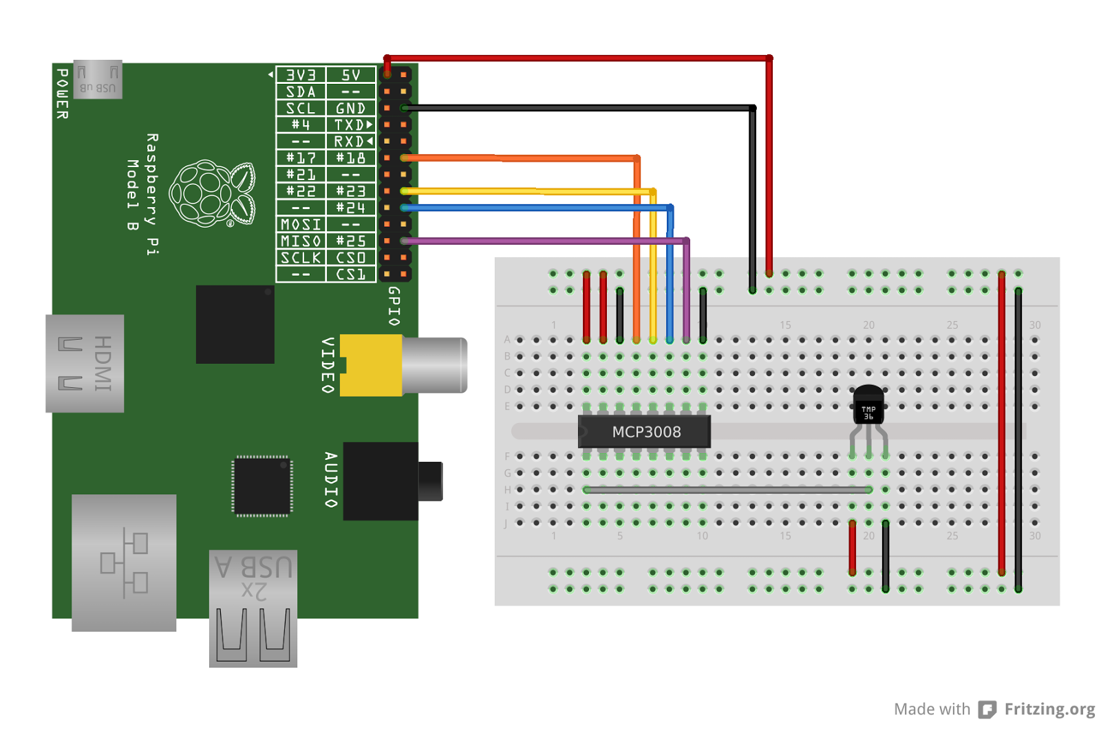
One of Raspberry Pi's limitations (compared to, say, an Arduino) is that it doesn't have analog pins, only digital ones. So to connect a sensor with analog output, you have to go through an analog-to-digital converter (ADC). The fine folks at Adafruit have written a tutorial on how to talk to an MCP3008 ADC from a Raspberry Pi to read the state of a potentiometer. I swapped the potentiometer for a TMP36 temperature sensor and now my Raspberry Pi knows what the temperature is.

Here's a nice looking diagram of how the connections go:


And here's a considerably more messy real-life shot:


I monitored the temperature in my room for some time and decided that it was boring. So then I put my new creation in the fridge to see how cold it is in there. Initially I wanted to put just the sensor in and keep the Raspberry Pi outside, but with all the cables going from the Pi to the breadboard, it was easier to just put everything inside with only the power cable going out. The Pi didn't mind the low temperature and I hope the small amount of heat it produces didn't affect the fridge and the measurement. And if you ever wondered whether wifi would work from inside a fridge, I'm happy to report that it works just fine.

Here's what it looked like inside my otherwise mostly empty fridge:


And here are the results:


(I averaged the data a bit, because the readings from the sensor were pretty noisy.)

It turns out that the temperature inside my fridge varies quite a bit, from around 3 °C to around 8 °C. The compressor runs for about 37% of the time (though that number probably depends on outside temperature and possibly the contents of the fridge).

Here's the script I used to read the temperature from the sensor, but it's mostly identical to the one in Adafruit's tutorial. One interesting thing about it is that it uses what's called a "bit banging" SPI implementation (the Raspberry Pi also has hardware SPI and we could use that just as well).

2012-08-26

Raspberry Pi controlled lamp

I'm a software guy and I'm scared of electronics. At the same time I find it exciting when software actually does something in the real world. (That's why I love Lego Mindstorms.) Home automation is my lifelong dream. I'd like to be able to use my computer to turn the lights on and off, roll up the window blinds and remotely control everything else that can be controlled.

That dream will have to wait, but today I used my Raspberry Pi to make a small proof of concept.


One of the many cool things about the Raspberry Pi is that it has some general purpose I/O pins exposed that can be used to communicate with the outside world using various protocols. The simplest thing you can do is to set a single pin to a high or low state. When combined with something called a relay, that is enough to control an electrical device plugged into a wall socket (or at least to turn it on and off). I used this relay from Seeedstudio. The relay has three pins (actually four, but one is unused), labeled VCC, GND and SIG. I connected VCC to the 5V pin on the Pi and GND to the ground pin. The SIG pin must be connected to one of several GPIO pins available. You can find a detailed description of Raspberry Pi's GPIO pins on the wiki. I connected the SIG pin from the relay to GPIO18, which is the sixth pin from the left in the top row.

Then I butchered a power strip. I removed the insulation from a segment of the cable, cut one of the cables inside, stripped some insulation from the ends and put them into the screw terminal on the relay. This is the part I was most uneasy about. You should obviously exercise caution when working with stuff that will be connected to mains voltage (extra caution when it actually is connected).

With everything attached, the only part remaining is software. The GPIO pins can be controlled through special files in the /sys filesystem, but I used a library called WiringPi. It includes the gpio command line tool, which makes working with GPIO pins easy.

First you have to configure the pin for output:

gpio export 18 out

Then you can set the state to high with:

gpio -g write 18 1

And to low with:

gpio -g write 18 0

Thus switching the relay on and off. I wrapped those commands in some trivial CGI scripts for the purpose of demonstration and controlled the lamp via a web browser.